How to Use Time of Flight Distance Ranging Sensor: Examples, Pinouts, and Specs
Introduction
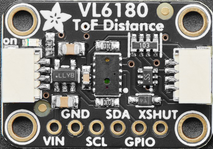
The Adafruit VL6180X Time of Flight (ToF) Distance Ranging Sensor is a compact and highly accurate sensor designed to measure the distance to an object by calculating the time it takes for a light pulse to travel to the object and back. This sensor uses infrared light and features an integrated proximity sensor and ambient light sensor, making it versatile for a wide range of applications.
Explore Projects Built with Time of Flight Distance Ranging Sensor

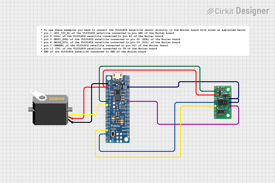
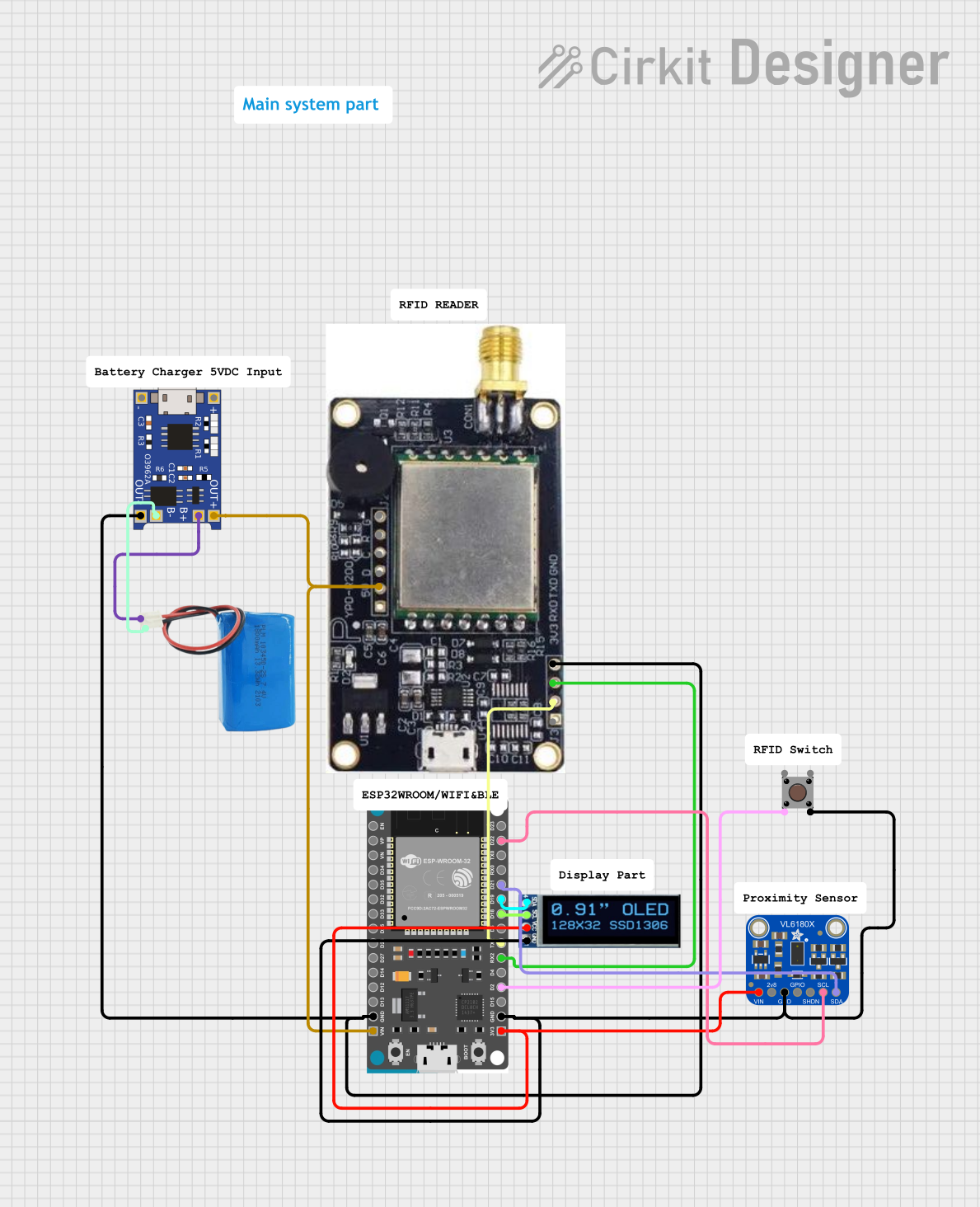
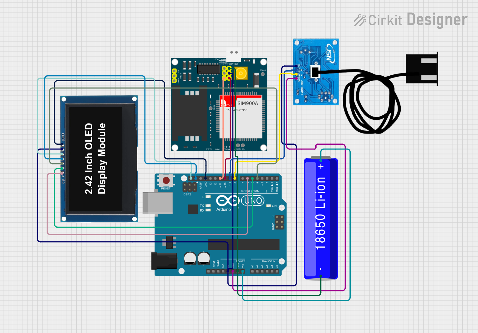
Explore Projects Built with Time of Flight Distance Ranging Sensor
Common Applications and Use Cases
- Proximity sensing: Detecting objects in robotics and automation systems.
- Gesture recognition: Enabling touchless control in consumer electronics.
- Obstacle detection: Used in drones, robots, and autonomous vehicles.
- Ambient light sensing: Adjusting screen brightness in smartphones and other devices.
- Industrial automation: Monitoring object presence or distance in manufacturing lines.
Technical Specifications
The VL6180X sensor is designed for low-power, high-accuracy distance measurements. Below are its key technical details:
Key Technical Details
- Operating Voltage: 2.8V to 5V (via onboard voltage regulator)
- Communication Interface: I²C (7-bit address: 0x29 by default)
- Distance Measurement Range: 5mm to 100mm (optimal performance)
- Ambient Light Sensor Range: 0 to 100k lux
- Measurement Accuracy: ±3mm (typical)
- Operating Temperature Range: -20°C to +70°C
- Current Consumption: ~1.7mA during ranging, ~0.5mA in standby
- Dimensions: 20mm x 18mm x 3mm (Adafruit breakout board)
Pin Configuration and Descriptions
The Adafruit VL6180X breakout board has the following pin layout:
| Pin Name | Description |
|---|---|
| VIN | Power input (2.8V to 5V). Connect to the 5V or 3.3V pin of your microcontroller. |
| GND | Ground. Connect to the ground of your circuit. |
| SCL | I²C clock line. Connect to the SCL pin of your microcontroller. |
| SDA | I²C data line. Connect to the SDA pin of your microcontroller. |
| GPIO | General-purpose input/output pin. Can be used for interrupts or custom logic. |
| SHDN | Shutdown pin. Pull low to put the sensor in low-power mode. |
Usage Instructions
The VL6180X sensor is easy to integrate into your projects using the I²C interface. Below are the steps to use the sensor effectively:
Connecting the Sensor
- Power the Sensor: Connect the VIN pin to a 3.3V or 5V power source and GND to ground.
- I²C Communication: Connect the SDA and SCL pins to the corresponding I²C pins on your microcontroller.
- Optional Connections:
- Use the GPIO pin for interrupt-based applications.
- Use the SHDN pin to enable or disable the sensor as needed.
Using the Sensor with Arduino UNO
The Adafruit VL6180X library simplifies the use of this sensor with Arduino. Follow these steps:
- Install the Adafruit VL6180X library via the Arduino Library Manager.
- Connect the sensor to the Arduino UNO as follows:
- VIN → 5V
- GND → GND
- SCL → A5 (I²C clock line)
- SDA → A4 (I²C data line)
- Upload the following example code to read distance measurements:
#include <Wire.h>
#include "Adafruit_VL6180X.h"

// Create an instance of the VL6180X sensor
Adafruit_VL6180X vl = Adafruit_VL6180X();

void setup() {
  Serial.begin(9600); // Initialize serial communication at 9600 baud
  Serial.println("Adafruit VL6180X test");

  if (!vl.begin()) {
    Serial.println("Failed to find VL6180X chip");
    while (1); // Halt execution if the sensor is not detected
  }
  Serial.println("VL6180X sensor found!");
}

void loop() {
  // Read the range (distance) in millimeters
  uint8_t range = vl.readRange();
  uint8_t status = vl.readRangeStatus();

  if (status == VL6180X_ERROR_NONE) {
    Serial.print("Range: ");
    Serial.print(range);
    Serial.println(" mm");
  } else {
    Serial.print("Range error: ");
    Serial.println(status);
  }

  delay(500); // Wait 500ms before the next reading
}
Important Considerations and Best Practices
- I²C Pull-Up Resistors: Ensure that your I²C bus has appropriate pull-up resistors (typically 4.7kΩ).
- Ambient Light Interference: Avoid using the sensor in direct sunlight or near strong infrared sources to maintain accuracy.
- Measurement Range: The sensor performs best within its specified range (5mm to 100mm). For distances beyond this range, accuracy may degrade.
- Mounting: Ensure the sensor is mounted securely and aligned properly for accurate measurements.
Troubleshooting and FAQs
Common Issues and Solutions
Sensor Not Detected:
- Ensure the I²C connections (SDA, SCL) are correct and secure.
- Verify the I²C address (default: 0x29). Use an I²C scanner sketch to confirm.
- Check the power supply voltage (2.8V to 5V).
Inaccurate Distance Measurements:
- Ensure the sensor is within its optimal range (5mm to 100mm).
- Avoid reflective or transparent surfaces, which may cause measurement errors.
- Minimize ambient light interference by shielding the sensor.
Intermittent Readings:
- Check for loose connections or poor solder joints.
- Ensure the I²C bus has proper pull-up resistors.
FAQs
Q: Can the VL6180X measure distances beyond 100mm?
A: While the sensor can detect objects slightly beyond 100mm, accuracy decreases significantly. For longer ranges, consider other ToF sensors like the VL53L0X.
Q: Can I use multiple VL6180X sensors on the same I²C bus?
A: Yes, but you must change the I²C address of each sensor. This can be done by configuring the sensor's address via software after initialization.
Q: How do I reduce power consumption?
A: Use the SHDN pin to put the sensor into low-power mode when not in use.
Q: Is the VL6180X suitable for outdoor use?
A: The sensor can be used outdoors but may be affected by strong sunlight or extreme temperatures. Consider additional shielding for better performance.
This concludes the documentation for the Adafruit VL6180X Time of Flight Distance Ranging Sensor.