
How to Use RadioMaster RP3 V1.5 ELRS: Examples, Pinouts, and Specs
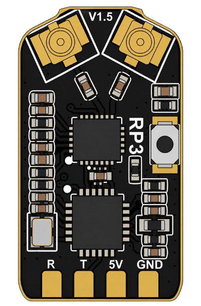
 Design with RadioMaster RP3 V1.5 ELRS in Cirkit Designer
Introduction
The RadioMaster RP3 V1.5 ELRS is a versatile and high-performance radio control transmitter module designed for use with ExpressLRS (ELRS) systems. It is widely recognized for its low latency, long-range communication capabilities, and seamless integration with RC (radio-controlled) applications. This module is ideal for hobbyists and professionals working with drones, RC planes, cars, and boats, offering reliable and efficient control in demanding environments.
Explore Projects Built with RadioMaster RP3 V1.5 ELRS
 Open Project in Cirkit Designer
 Open Project in Cirkit Designer
 Open Project in Cirkit Designer
 Open Project in Cirkit Designer
Explore Projects Built with RadioMaster RP3 V1.5 ELRS
Open Project in Cirkit DesignerOpen Project in Cirkit DesignerOpen Project in Cirkit DesignerOpen Project in Cirkit DesignerCommon Applications and Use Cases
- Drone Racing: Provides low-latency control for high-speed racing drones.
- RC Planes and Helicopters: Ensures stable and long-range communication for precise control.
- RC Cars and Boats: Offers reliable connectivity for ground and water-based RC vehicles.
- FPV (First-Person View) Systems: Works seamlessly with FPV setups for immersive experiences.
- Hobbyist Projects: Suitable for custom RC projects requiring robust and flexible communication.
Technical Specifications
The RadioMaster RP3 V1.5 ELRS module is designed to meet the needs of modern RC enthusiasts. Below are its key technical details:
Key Technical Details
| Parameter | Specification |
|---|---|
| Protocol | ExpressLRS (ELRS) |
| Frequency Range | 2.4 GHz |
| Output Power | Adjustable: 10 mW, 25 mW, 100 mW, 250 mW |
| Input Voltage | 5V (via compatible transmitter) |
| Latency | Ultra-low (as low as 4 ms) |
| Antenna Connector | SMA (Standard) |
| Compatibility | OpenTX/EdgeTX transmitters with JR bay |
| Dimensions | 60 mm x 45 mm x 15 mm |
| Weight | 30 g |
Pin Configuration and Descriptions
The RadioMaster RP3 V1.5 ELRS module connects to transmitters via a JR module bay. Below is the pin configuration for the JR interface:
| Pin | Name | Description |
|---|---|---|
| 1 | VCC | Power input (5V) |
| 2 | GND | Ground |
| 3 | TX | UART Transmit (communication with transmitter) |
| 4 | RX | UART Receive (communication with transmitter) |
| 5 | PPM | Pulse Position Modulation input (optional) |
| 6 | NC | Not connected |
Usage Instructions
How to Use the Component in a Circuit
- Install the Module: Insert the RadioMaster RP3 V1.5 ELRS module into the JR bay of a compatible transmitter (e.g., OpenTX or EdgeTX-based transmitters).
- Connect the Antenna: Attach the included SMA antenna securely to the module to ensure optimal signal transmission and reception.
- Power On the Transmitter: Turn on the transmitter to power the module. Ensure the transmitter is configured to use the ELRS protocol.
- Bind the Receiver: Follow the ExpressLRS binding procedure to pair the module with a compatible ELRS receiver. Typically, this involves:
- Powering on the receiver in binding mode.
- Activating the binding process from the transmitter's menu.
- Configure Settings: Use the transmitter's interface to adjust settings such as output power, frequency, and failsafe behavior.
- Test the System: Verify the connection by testing the control response of your RC model.
Important Considerations and Best Practices
- Antenna Placement: Always ensure the antenna is securely connected before powering on the module to avoid damage to the RF circuitry.
- Output Power: Use the lowest output power necessary for your application to minimize interference and conserve energy.
- Firmware Updates: Keep the module's firmware up to date with the latest ExpressLRS releases for improved performance and features.
- Cooling: Avoid prolonged use at high output power (e.g., 250 mW) without adequate ventilation to prevent overheating.
- Range Testing: Perform a range test before operating your RC model to ensure a reliable connection.
Example Code for Arduino UNO Integration
While the RadioMaster RP3 V1.5 ELRS is not directly connected to an Arduino, you can use an Arduino to simulate a PPM signal for testing purposes. Below is an example code snippet:
// Example: Generate a PPM signal for testing the RP3 V1.5 ELRS module
// Connect the Arduino's digital pin 9 to the PPM input pin of the module.

#define PPM_PIN 9  // Pin to output the PPM signal
#define CHANNELS 8 // Number of channels
#define PPM_FRAME_LENGTH 22500 // Total frame length in microseconds
#define PULSE_LENGTH 300       // Pulse length in microseconds

int channelValues[CHANNELS] = {1500, 1500, 1500, 1500, 1500, 1500, 1500, 1500};

void setup() {
  pinMode(PPM_PIN, OUTPUT);
  digitalWrite(PPM_PIN, LOW);
}

void loop() {
  unsigned long frameStart = micros();
  for (int i = 0; i < CHANNELS; i++) {
    // Generate a pulse for each channel
    digitalWrite(PPM_PIN, HIGH);
    delayMicroseconds(PULSE_LENGTH);
    digitalWrite(PPM_PIN, LOW);
    delayMicroseconds(channelValues[i] - PULSE_LENGTH);
  }
  // Fill the remaining frame time with a low signal
  delayMicroseconds(PPM_FRAME_LENGTH - (micros() - frameStart));
}
Troubleshooting and FAQs
Common Issues Users Might Face
Module Not Powering On:
- Cause: Improper installation or faulty JR bay connection.
- Solution: Ensure the module is securely inserted into the JR bay and the transmitter is powered on.
Binding Fails:
- Cause: Receiver not in binding mode or mismatched firmware versions.
- Solution: Verify the receiver is in binding mode and ensure both the module and receiver are running compatible firmware versions.
Poor Range or Signal Loss:
- Cause: Antenna not connected or interference in the environment.
- Solution: Check the antenna connection and avoid operating in areas with high RF interference.
Overheating:
- Cause: Prolonged use at high output power without ventilation.
- Solution: Reduce output power or ensure adequate airflow around the module.
Solutions and Tips for Troubleshooting
- Firmware Compatibility: Always use the same version of ExpressLRS firmware on both the module and receiver.
- Diagnostic Tools: Use the transmitter's diagnostic tools to monitor signal strength (RSSI) and link quality.
- Factory Reset: If issues persist, perform a factory reset on the module and reconfigure it from scratch.
By following this documentation, users can effectively utilize the RadioMaster RP3 V1.5 ELRS module for their RC applications while avoiding common pitfalls.