How to Use 4xAA_bare: Examples, Pinouts, and Specs

Introduction
The 4xAA Battery Holder is a versatile and essential component designed to hold four AA batteries. It is commonly used to provide a portable power source for various electronic projects. This battery holder is ideal for hobbyists, students, and professionals who need a reliable and convenient way to power their circuits and devices.
Explore Projects Built with 4xAA_bare
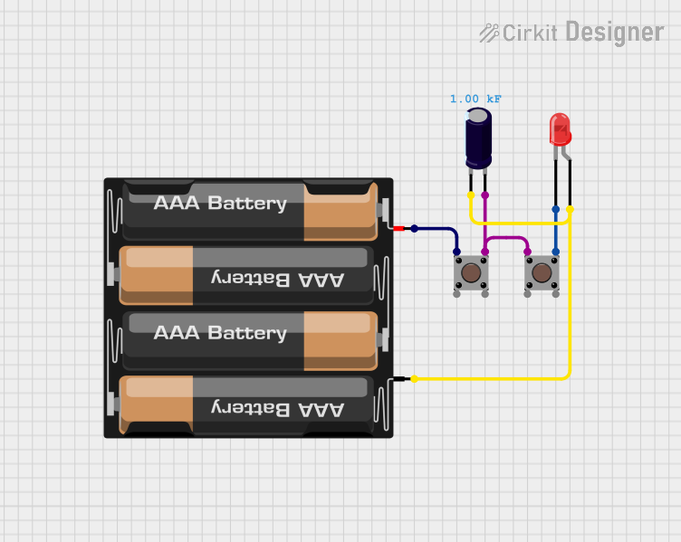
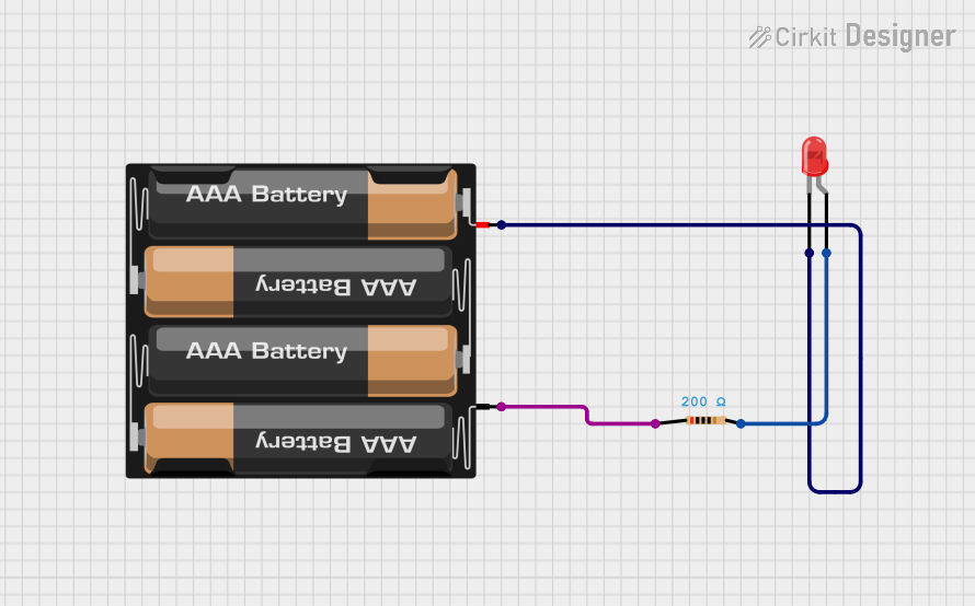
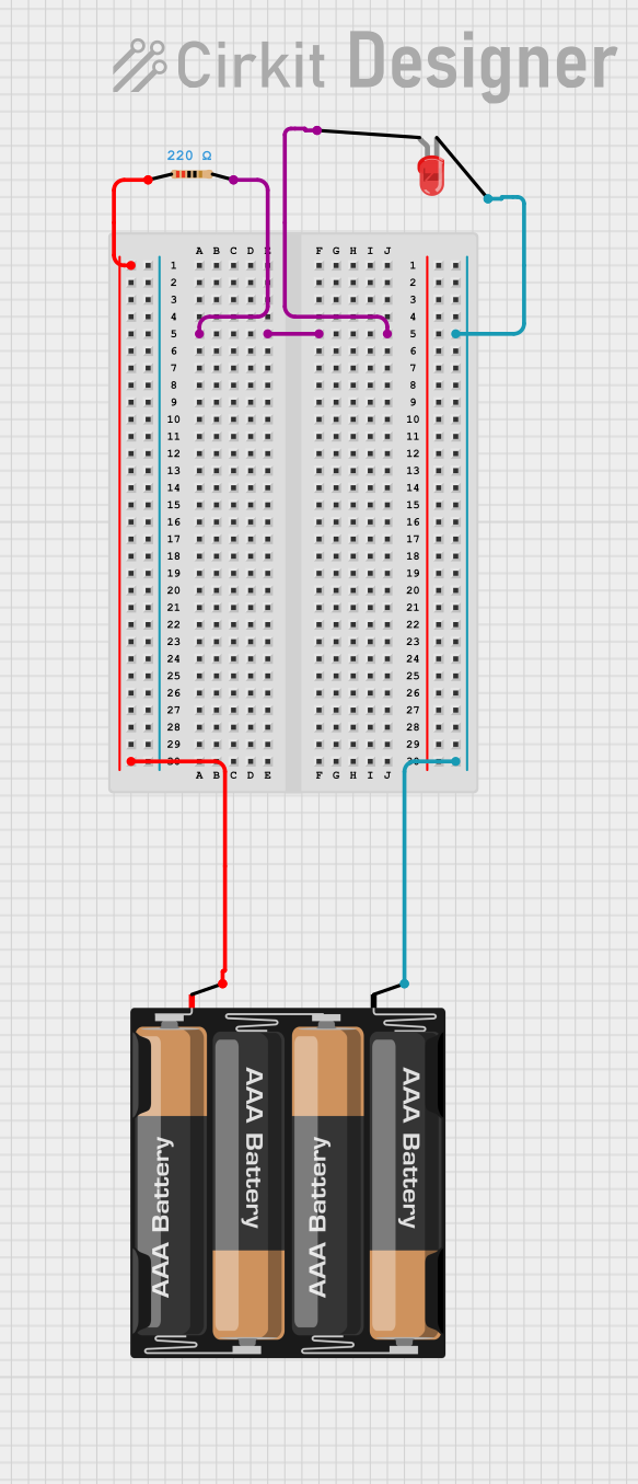

Explore Projects Built with 4xAA_bare
Common Applications and Use Cases
- Portable Electronics: Powering small electronic devices and gadgets.
- Prototyping: Providing a temporary power source for breadboard and prototyping projects.
- Robotics: Supplying power to small robots and motorized projects.
- Arduino Projects: Serving as a power source for Arduino-based projects and other microcontroller applications.
Technical Specifications
The following table outlines the key technical details of the 4xAA Battery Holder:
| Specification | Description |
|---|---|
| Battery Type | AA (1.5V each) |
| Number of Batteries | 4 |
| Total Voltage | 6V (when using 1.5V AA batteries) |
| Current Rating | Depends on the batteries used |
| Material | Plastic housing with metal contacts |
| Dimensions | Varies by manufacturer, typically 60mm x 30mm x 15mm |
| Weight | Varies by manufacturer, typically 20-30 grams |
Pin Configuration and Descriptions
The 4xAA Battery Holder typically has two wires for connection:
| Pin/Lead | Description |
|---|---|
| Red Wire | Positive terminal (+6V) |
| Black Wire | Negative terminal (Ground) |
Usage Instructions
How to Use the Component in a Circuit
Insert Batteries:
- Place four AA batteries into the holder, ensuring correct polarity as indicated.
Connect to Circuit:
- Connect the red wire (positive terminal) to the positive power rail of your circuit.
- Connect the black wire (negative terminal) to the ground (GND) of your circuit.
Powering an Arduino UNO:
- Connect the red wire to the VIN pin on the Arduino UNO.
- Connect the black wire to the GND pin on the Arduino UNO.
Important Considerations and Best Practices
- Polarity: Always ensure correct polarity when inserting batteries to avoid damage.
- Battery Type: Use only AA batteries. Mixing different types or brands can lead to inconsistent performance.
- Heat: Avoid short circuits, as they can cause the batteries to overheat.
- Storage: Remove batteries when not in use for extended periods to prevent leakage and corrosion.
Troubleshooting and FAQs
Common Issues Users Might Face
No Power Output:
- Solution: Check battery orientation and ensure all batteries are properly inserted.
- Solution: Verify connections to the circuit are secure and correct.
Intermittent Power:
- Solution: Inspect the battery holder for loose contacts or damaged wires.
- Solution: Ensure batteries are not depleted and replace if necessary.
Overheating:
- Solution: Check for short circuits in the connected circuit.
- Solution: Ensure the battery holder is not overloaded beyond its current rating.
FAQs
Q1: Can I use rechargeable AA batteries with this holder?
- A1: Yes, you can use rechargeable AA batteries. However, note that the total voltage will be lower (typically 4.8V for NiMH batteries).
Q2: How do I know if the batteries are inserted correctly?
- A2: Follow the polarity markings inside the battery holder. The flat end of the battery is the negative terminal, and the raised end is the positive terminal.
Q3: Can I use this battery holder with other microcontrollers?
- A3: Yes, the 4xAA Battery Holder can be used with various microcontrollers, provided the voltage and current requirements are compatible.
Example Code for Arduino UNO
Here is a simple example code to read the voltage from the 4xAA Battery Holder using an Arduino UNO:
const int batteryPin = A0; // Analog pin to read battery voltage
float batteryVoltage;

void setup() {
  Serial.begin(9600); // Initialize serial communication
}

void loop() {
  int sensorValue = analogRead(batteryPin); // Read the analog input
  batteryVoltage = sensorValue * (5.0 / 1023.0) * 2; // Convert to voltage
  // The factor of 2 is used because the voltage divider halves the voltage
  Serial.print("Battery Voltage: ");
  Serial.print(batteryVoltage);
  Serial.println(" V");
  delay(1000); // Wait for 1 second before next reading
}
Note: This code assumes a voltage divider circuit is used to step down the 6V to a readable range for the Arduino's analog input.
By following this documentation, users can effectively utilize the 4xAA Battery Holder in their electronic projects, ensuring reliable and portable power for their circuits.