How to Use DC worm gear motor : Examples, Pinouts, and Specs
Introduction
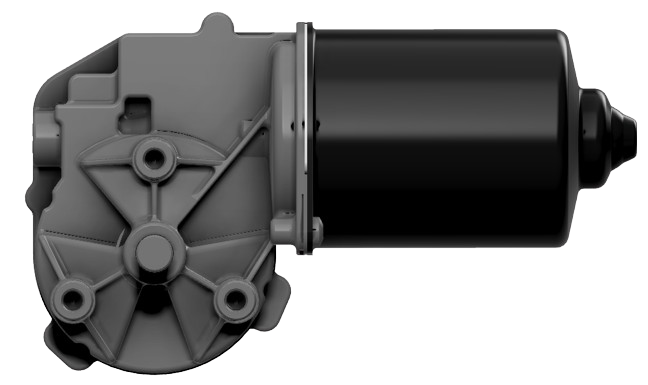
A DC worm gear motor is an electric motor that incorporates a worm gear mechanism to achieve speed reduction and torque amplification. This type of motor is widely used in applications requiring low-speed, high-torque output, and precise control. The worm gear mechanism ensures smooth operation, self-locking capabilities, and high efficiency, making it ideal for tasks such as lifting, rotating, or driving heavy loads.
Explore Projects Built with DC worm gear motor
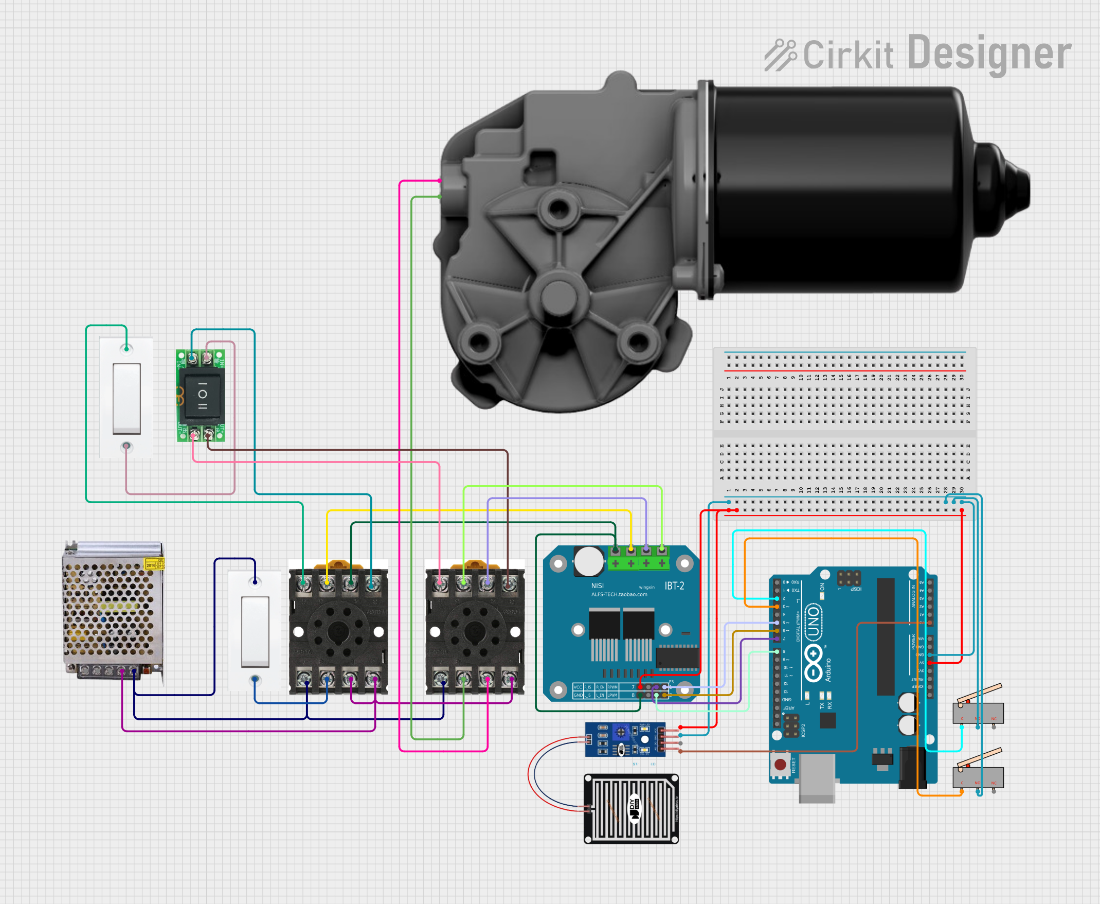

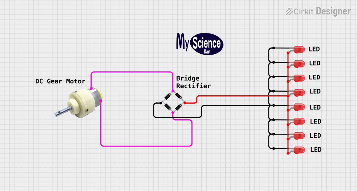
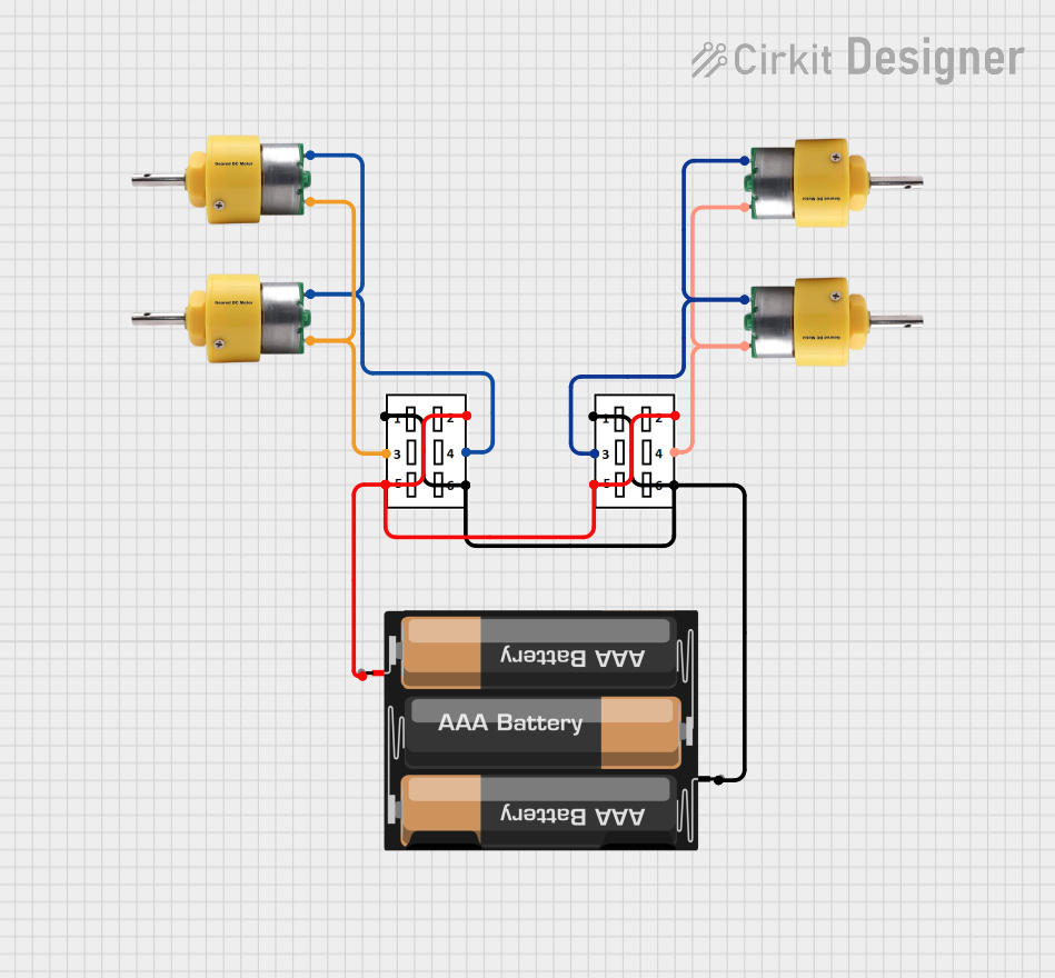
Explore Projects Built with DC worm gear motor
Common Applications and Use Cases
- Robotic arms and automation systems
- Conveyor belts and material handling equipment
- Electric gates and door openers
- Automotive applications (e.g., power seats, wipers)
- Industrial machinery requiring high torque at low speeds
Technical Specifications
Key Technical Details
| Parameter | Value/Range |
|---|---|
| Operating Voltage | 6V - 24V DC |
| Rated Torque | 5 Nm - 50 Nm (varies by model) |
| No-Load Speed | 5 RPM - 200 RPM |
| Gear Ratio | 20:1 to 100:1 (depending on model) |
| Current Consumption | 0.5A - 5A (depending on load) |
| Motor Type | Brushed DC Motor |
| Shaft Diameter | 6mm - 12mm |
| Self-Locking Capability | Yes (depends on gear ratio) |
| Operating Temperature | -10°C to 60°C |
Pin Configuration and Descriptions
Most DC worm gear motors have two terminals for power input. The polarity of the input voltage determines the direction of rotation.
| Pin/Terminal | Description |
|---|---|
| Terminal 1 | Positive voltage input (for clockwise rotation) |
| Terminal 2 | Negative voltage input (for counterclockwise rotation) |
Note: Reversing the polarity of the terminals will reverse the motor's direction.
Usage Instructions
How to Use the Component in a Circuit
- Power Supply: Connect the motor to a DC power supply within the specified voltage range (e.g., 12V DC). Ensure the power supply can provide sufficient current for the motor's operation.
- Direction Control: Use an H-bridge motor driver (e.g., L298N or L293D) to control the motor's direction and speed. The H-bridge allows you to reverse the polarity of the voltage applied to the motor.
- Speed Control: Implement Pulse Width Modulation (PWM) using a microcontroller (e.g., Arduino UNO) to control the motor's speed.
- Mounting: Secure the motor using appropriate brackets or mounts to prevent vibration or misalignment during operation.
Important Considerations and Best Practices
- Avoid Overloading: Do not exceed the motor's rated torque to prevent damage to the gear mechanism.
- Heat Dissipation: Ensure proper ventilation or heat sinks if the motor operates continuously under high loads.
- Self-Locking: Take advantage of the worm gear's self-locking feature to hold loads in place without additional braking mechanisms.
- Polarity Check: Double-check the polarity of the power supply to avoid unintentional reverse rotation.
Example: Connecting to an Arduino UNO
Below is an example of how to control a DC worm gear motor using an Arduino UNO and an L298N motor driver.
Circuit Diagram
- Connect the motor terminals to the output pins of the L298N motor driver (OUT1 and OUT2).
- Connect the L298N's input pins (IN1 and IN2) to Arduino digital pins 9 and 10, respectively.
- Connect the L298N's enable pin (ENA) to Arduino PWM pin 6 for speed control.
Arduino Code
// Define motor control pins
const int IN1 = 9;  // Motor direction control pin 1
const int IN2 = 10; // Motor direction control pin 2
const int ENA = 6;  // Motor speed control (PWM) pin

void setup() {
  // Set motor control pins as outputs
  pinMode(IN1, OUTPUT);
  pinMode(IN2, OUTPUT);
  pinMode(ENA, OUTPUT);
}

void loop() {
  // Rotate motor clockwise at 50% speed
  digitalWrite(IN1, HIGH);  // Set IN1 high
  digitalWrite(IN2, LOW);   // Set IN2 low
  analogWrite(ENA, 128);    // Set speed to 50% (128 out of 255)
  delay(5000);              // Run for 5 seconds

  // Rotate motor counterclockwise at 75% speed
  digitalWrite(IN1, LOW);   // Set IN1 low
  digitalWrite(IN2, HIGH);  // Set IN2 high
  analogWrite(ENA, 192);    // Set speed to 75% (192 out of 255)
  delay(5000);              // Run for 5 seconds

  // Stop the motor
  digitalWrite(IN1, LOW);   // Set IN1 low
  digitalWrite(IN2, LOW);   // Set IN2 low
  analogWrite(ENA, 0);      // Set speed to 0
  delay(2000);              // Wait for 2 seconds
}
Troubleshooting and FAQs
Common Issues and Solutions
Motor Does Not Rotate
- Cause: Insufficient power supply or incorrect wiring.
- Solution: Verify the power supply voltage and current. Check all connections.
Motor Rotates in the Wrong Direction
- Cause: Polarity of the input voltage is reversed.
- Solution: Swap the connections of the motor terminals or adjust the H-bridge control logic.
Motor Overheats
- Cause: Prolonged operation under high load or insufficient ventilation.
- Solution: Reduce the load or provide better cooling.
Motor Vibrates or Makes Noise
- Cause: Loose mounting or misaligned shaft.
- Solution: Secure the motor properly and check the alignment of the shaft.
FAQs
Q: Can I use a DC worm gear motor with a battery?
- A: Yes, as long as the battery provides the required voltage and current.
Q: Is the motor waterproof?
- A: Most DC worm gear motors are not waterproof. Use a waterproof enclosure for outdoor applications.
Q: How do I calculate the torque required for my application?
- A: Determine the load's weight and the distance from the axis of rotation. Use the formula: Torque = Force × Distance.
Q: Can I control multiple motors with one Arduino?
- A: Yes, you can control multiple motors using multiple motor drivers or a motor driver with multiple channels. Ensure the Arduino has enough PWM pins for speed control.