How to Use L298N 4WD Moror driver: Examples, Pinouts, and Specs
Introduction
The L298N 4WD Motor Driver, manufactured by Arduino (Part ID: L298N 4WD), is a dual H-bridge motor driver module designed to control the direction and speed of DC motors and stepper motors. It is capable of driving two motors simultaneously, making it an essential component for robotics and automation projects. The module is widely used in applications such as robotic cars, conveyor systems, and other motorized systems requiring precise control.
Explore Projects Built with L298N 4WD Moror driver


Explore Projects Built with L298N 4WD Moror driver
Common Applications:
- Robotic vehicles (e.g., 4WD robotic cars)
- Conveyor belt systems
- Automated gates and doors
- Stepper motor control in CNC machines
- DIY robotics and hobby projects
Technical Specifications
The L298N 4WD Motor Driver is designed to handle a wide range of motor control tasks. Below are its key technical details:
Key Specifications:
| Parameter | Value |
|---|---|
| Operating Voltage | 5V to 35V |
| Logic Voltage | 5V |
| Maximum Output Current | 2A per channel (continuous) |
| Peak Output Current | 3A per channel (short duration) |
| Number of Channels | 2 (dual H-bridge) |
| Control Logic Levels | High: 5V, Low: 0V |
| PWM Frequency | Up to 20 kHz |
| Dimensions | 43mm x 43mm x 27mm |
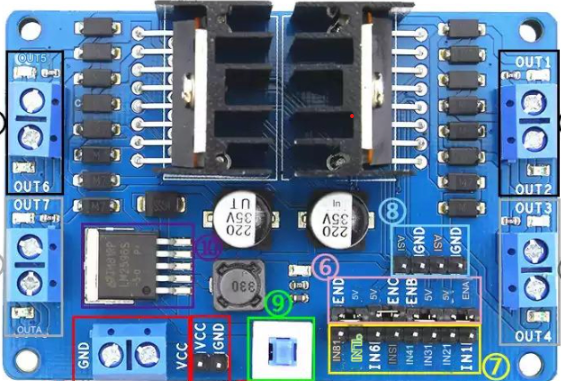
Pin Configuration:
The L298N module has several pins and terminals for motor control and power input. Below is the pin configuration:
| Pin/Terminal Name | Description |
|---|---|
IN1 |
Input pin to control Motor A direction (logic HIGH/LOW). |
IN2 |
Input pin to control Motor A direction (logic HIGH/LOW). |
IN3 |
Input pin to control Motor B direction (logic HIGH/LOW). |
IN4 |
Input pin to control Motor B direction (logic HIGH/LOW). |
ENA |
PWM input to control Motor A speed. |
ENB |
PWM input to control Motor B speed. |
VCC |
Motor power supply (5V to 35V). |
GND |
Ground connection. |
5V |
Logic voltage output (can power external microcontrollers if jumper is set). |
Jumper Settings:
- Enable Jumpers (ENA/ENB): When the jumpers are in place, the motors run at full speed. Removing the jumpers allows speed control via PWM signals.
- 5V Jumper: If the motor power supply (VCC) is greater than 7V, the onboard voltage regulator provides 5V logic power. If using an external 5V logic supply, remove this jumper.
Usage Instructions
The L298N 4WD Motor Driver is straightforward to use in a circuit. Below are the steps and best practices for integrating it into your project.
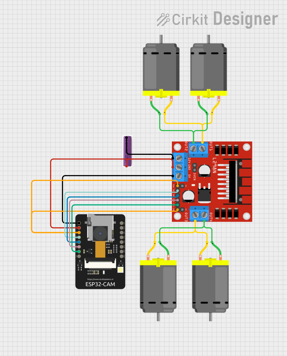
Connecting the L298N to Motors and Power:
Power Supply:
- Connect the
VCCterminal to the motor power supply (5V to 35V). - Connect the
GNDterminal to the ground of the power supply and the microcontroller. - If using an external 5V logic supply, connect it to the
5Vpin and remove the 5V jumper.
- Connect the
Motor Connections:
- Connect the terminals of Motor A to the
OUT1andOUT2pins. - Connect the terminals of Motor B to the
OUT3andOUT4pins.
- Connect the terminals of Motor A to the
Control Pins:
- Connect
IN1andIN2to the microcontroller pins for Motor A direction control. - Connect
IN3andIN4to the microcontroller pins for Motor B direction control. - Connect
ENAandENBto PWM-capable pins on the microcontroller for speed control.
- Connect
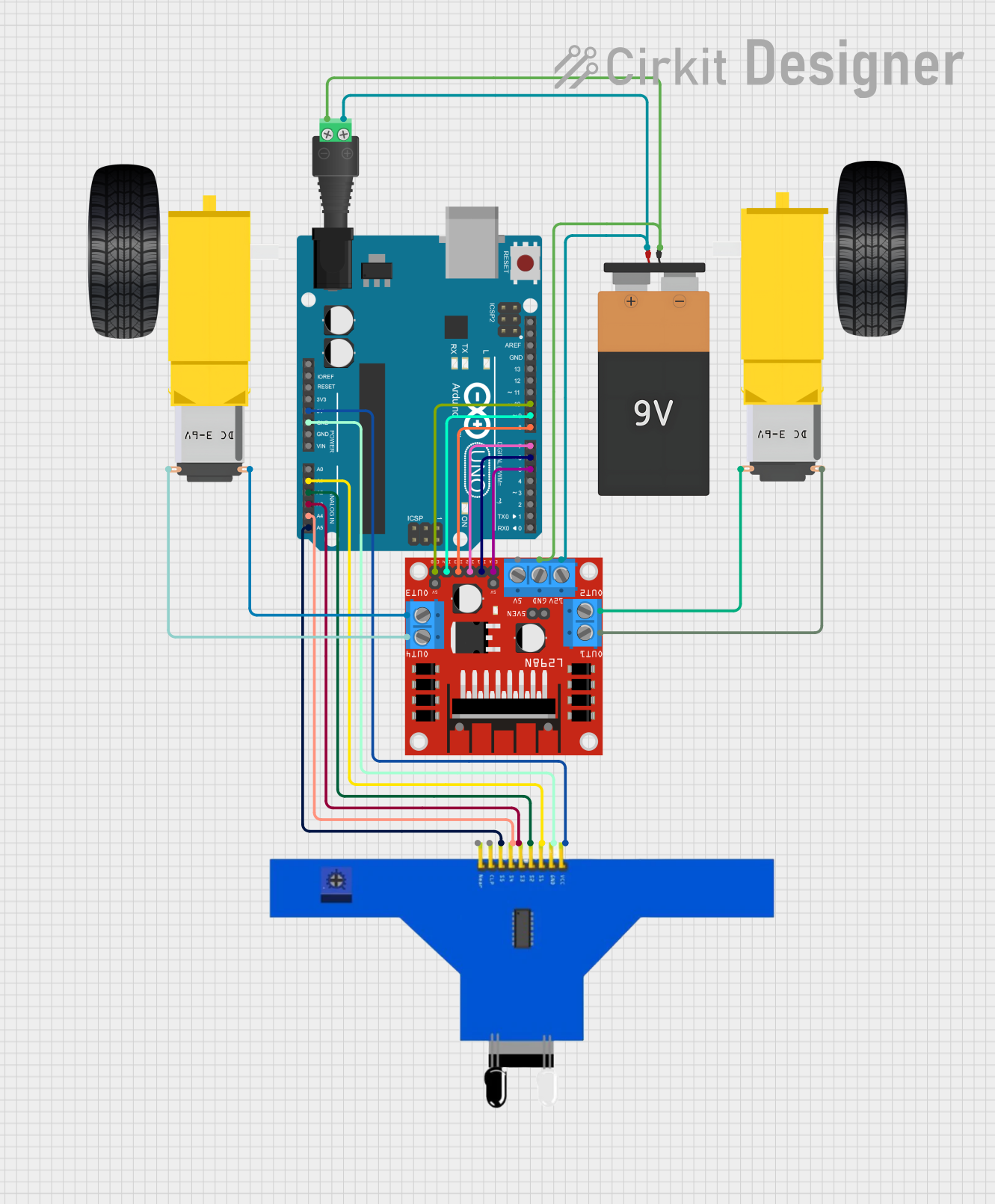
Arduino UNO Example Code:
Below is an example of how to control two DC motors using the L298N module with an Arduino UNO.
// Define motor control pins
#define IN1 7  // Motor A direction control pin 1
#define IN2 6  // Motor A direction control pin 2
#define ENA 5  // Motor A speed control (PWM)
#define IN3 4  // Motor B direction control pin 1
#define IN4 3  // Motor B direction control pin 2
#define ENB 2  // Motor B speed control (PWM)

void setup() {
  // Set motor control pins as outputs
  pinMode(IN1, OUTPUT);
  pinMode(IN2, OUTPUT);
  pinMode(ENA, OUTPUT);
  pinMode(IN3, OUTPUT);
  pinMode(IN4, OUTPUT);
  pinMode(ENB, OUTPUT);
}

void loop() {
  // Motor A: Forward at 50% speed
  digitalWrite(IN1, HIGH);
  digitalWrite(IN2, LOW);
  analogWrite(ENA, 128); // 50% duty cycle (0-255)

  // Motor B: Backward at 75% speed
  digitalWrite(IN3, LOW);
  digitalWrite(IN4, HIGH);
  analogWrite(ENB, 192); // 75% duty cycle (0-255)

  delay(2000); // Run motors for 2 seconds

  // Stop both motors
  digitalWrite(IN1, LOW);
  digitalWrite(IN2, LOW);
  digitalWrite(IN3, LOW);
  digitalWrite(IN4, LOW);
  analogWrite(ENA, 0);
  analogWrite(ENB, 0);

  delay(2000); // Wait for 2 seconds
}
Best Practices:
- Use a heat sink on the L298N module if driving motors with high current for extended periods.
- Ensure the motor power supply voltage matches the motor's rated voltage.
- Use appropriate decoupling capacitors to reduce noise in the circuit.
- Avoid exceeding the maximum current rating (2A per channel) to prevent damage.
Troubleshooting and FAQs
Common Issues and Solutions:
Motors not running:
- Verify all connections, especially the power supply and ground.
- Check if the control pins (
IN1,IN2, etc.) are receiving the correct logic signals. - Ensure the enable pins (
ENA,ENB) are properly configured (either via jumpers or PWM).
Motors running in the wrong direction:
- Swap the connections of
IN1andIN2(orIN3andIN4) to reverse the motor direction. - Verify the logic levels sent to the control pins.
- Swap the connections of
Module overheating:
- Attach a heat sink to the L298N chip.
- Reduce the motor load or use motors with lower current requirements.
PWM not controlling speed:
- Ensure the enable jumpers are removed if using PWM.
- Verify the PWM signal is being generated correctly by the microcontroller.
FAQs:
Q: Can the L298N drive stepper motors?
A: Yes, the L298N can control stepper motors by using both H-bridge channels. However, additional logic may be required to sequence the motor phases correctly.
Q: Can I power the Arduino UNO from the L298N module?
A: Yes, if the motor power supply (VCC) is greater than 7V, the onboard voltage regulator can provide 5V to the Arduino UNO via the 5V pin. Ensure the 5V jumper is in place.
Q: What is the maximum motor voltage the L298N can handle?
A: The L298N can handle motor voltages up to 35V. Ensure your motor's voltage rating is within this range.
Q: Can I control more than two motors with the L298N?
A: No, the L298N is designed to control up to two DC motors or one stepper motor. For more motors, additional modules are required.