How to Use Cable Adapter Module: Examples, Pinouts, and Specs
Introduction
The Cable Adapter Module by DFRobot (Part ID: Cable Adapter Module) is a versatile device designed to facilitate the connection and communication between different types of cables. It acts as a bridge, enabling seamless integration of various electronic devices and systems. This module is particularly useful in prototyping, testing, and applications where multiple cable standards need to interface.
Explore Projects Built with Cable Adapter Module


Explore Projects Built with Cable Adapter Module
Common Applications and Use Cases
- Prototyping and testing electronic circuits
- Connecting devices with incompatible cable types
- Bridging communication between different systems
- Educational projects and DIY electronics
- Industrial automation and control systems
Technical Specifications
The Cable Adapter Module is designed to be robust and easy to use, with the following key specifications:
| Parameter | Value |
|---|---|
| Manufacturer | DFRobot |
| Part ID | Cable Adapter Module |
| Operating Voltage | 3.3V to 5V |
| Maximum Current | 1A |
| Supported Cable Types | JST, DuPont, PH2.0, XH2.54, etc. |
| Dimensions | 30mm x 20mm x 10mm |
| Weight | 5g |
| Operating Temperature | -20°C to 70°C |
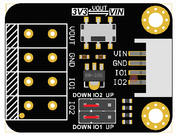
Pin Configuration and Descriptions
The module features multiple connectors to support various cable types. Below is the pin configuration:
| Connector Type | Pin Count | Description |
|---|---|---|
| JST | 4 | Standard JST connector for signal/power |
| DuPont | 4 | Commonly used for breadboard connections |
| PH2.0 | 4 | Compact connector for small devices |
| XH2.54 | 4 | Larger connector for higher currents |
Usage Instructions
How to Use the Cable Adapter Module in a Circuit
- Identify the Cable Types: Determine the cable types you need to connect (e.g., JST to DuPont).
- Connect the Cables: Plug the cables into the appropriate connectors on the module. Ensure the polarity and pin alignment are correct.
- Power the Module: Supply the module with a voltage between 3.3V and 5V. This can be done via an external power source or directly from a microcontroller like an Arduino.
- Verify Connections: Double-check all connections to ensure proper communication between devices.
Important Considerations and Best Practices
- Polarity: Always verify the polarity of the cables before connecting them to avoid damage to the module or connected devices.
- Current Limitations: Do not exceed the maximum current rating of 1A to prevent overheating or damage.
- Secure Connections: Ensure all cables are securely plugged in to avoid intermittent connections.
- Compatibility: Confirm that the connected devices are compatible in terms of voltage and communication protocols.
Example: Using the Cable Adapter Module with an Arduino UNO
The Cable Adapter Module can be used to connect sensors or other peripherals to an Arduino UNO. Below is an example of connecting a sensor with a JST connector to the Arduino:
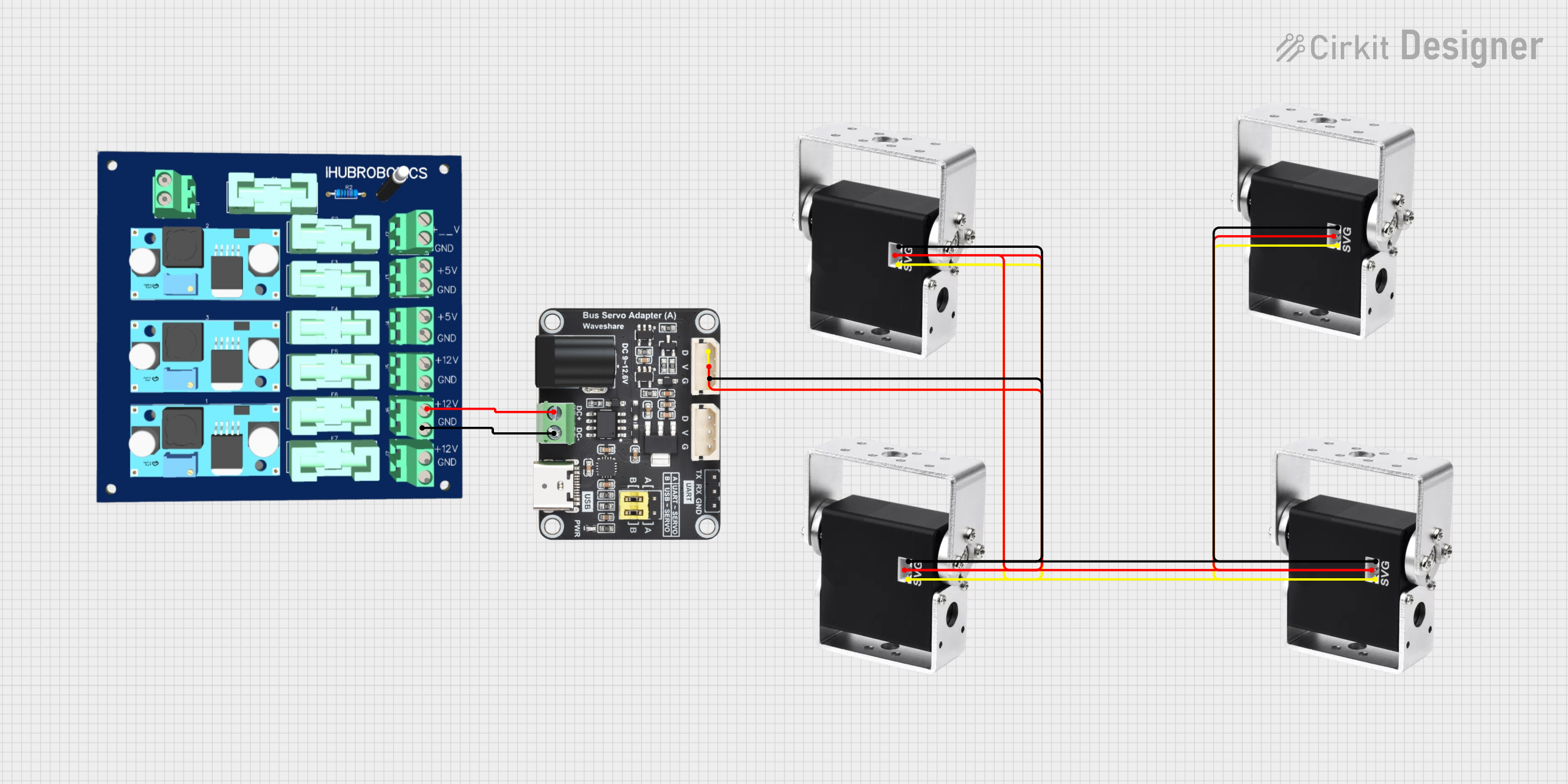
Circuit Diagram
- Connect the sensor's JST cable to the module's JST connector.
- Use DuPont cables to connect the module to the Arduino UNO:
- VCC to 5V
- GND to GND
- Signal to a digital or analog pin (e.g., A0)
Arduino Code Example
// Example code for reading a sensor connected via the Cable Adapter Module
const int sensorPin = A0; // Analog pin connected to the sensor signal
int sensorValue = 0;      // Variable to store the sensor reading

void setup() {
  Serial.begin(9600); // Initialize serial communication at 9600 baud
  pinMode(sensorPin, INPUT); // Set the sensor pin as input
}

void loop() {
  sensorValue = analogRead(sensorPin); // Read the sensor value
  Serial.print("Sensor Value: ");      // Print the sensor value to the serial monitor
  Serial.println(sensorValue);
  delay(500); // Wait for 500ms before the next reading
}
Troubleshooting and FAQs
Common Issues and Solutions
No Signal Detected
- Cause: Incorrect cable connection or loose connection.
- Solution: Verify that the cables are securely connected and aligned correctly.
Overheating
- Cause: Exceeding the maximum current rating of 1A.
- Solution: Reduce the load or ensure the connected devices do not draw excessive current.
Intermittent Connections
- Cause: Loose or poorly seated cables.
- Solution: Ensure all cables are firmly plugged in and check for damaged connectors.
Device Not Responding
- Cause: Voltage mismatch or incompatible devices.
- Solution: Verify that the connected devices operate at the same voltage level and are compatible.
FAQs
Q: Can I use this module with 12V devices?
A: No, the module is designed to operate at 3.3V to 5V. Using 12V may damage the module.
Q: Is the module compatible with I2C or SPI communication?
A: Yes, the module can be used to connect devices that communicate via I2C or SPI, provided the pinout matches.
Q: Can I use this module for power delivery only?
A: Yes, the module can be used to deliver power between devices, as long as the current does not exceed 1A.
Q: How do I clean the connectors?
A: Use a soft, dry cloth or compressed air to clean the connectors. Avoid using liquids or abrasive materials.
This concludes the documentation for the Cable Adapter Module by DFRobot. For further assistance, refer to the manufacturer's website or contact their support team.