Cirkit Designer Logo
Cirkit Designer
Your all-in-one circuit design IDE
Home / 
Component Documentation

How to Use PS2 Joystick: Examples, Pinouts, and Specs

Image of PS2 Joystick
Cirkit Designer LogoDesign with PS2 Joystick in Cirkit Designer

Introduction

The PS2 Joystick module is a versatile input device commonly used in electronic projects for manual control. It operates as a two-axis analog joystick providing positional feedback through potentiometers and includes a push-button for additional interface options. This joystick is widely used in gaming consoles, robotics, and various DIY projects where user input for control is required.

Explore Projects Built with PS2 Joystick

Use Cirkit Designer to design, explore, and prototype these projects online. Some projects support real-time simulation. Click "Open Project" to start designing instantly!
Raspberry Pi Pico-based PS2 Controller Emulator with ADS1115 Analog Input
Image of PS2Pico: A project utilizing PS2 Joystick in a practical application
This circuit appears to be a game controller interface that uses a Raspberry Pi Pico microcontroller to emulate a PS2 controller, interfacing with a PS2 joystick and a PS2 console cable. The ADS1115 analog-to-digital converter is used to read the joystick's analog signals, and the microcontroller's SPI and I2C interfaces are utilized for communication with the PS2 console and the ADS1115, respectively. Additionally, an NPN transistor and a resistor are configured to handle the PS2 controller's acknowledge signal.
Cirkit Designer LogoOpen Project in Cirkit Designer
Arduino Nano Joystick-Controlled Bluetooth Module with Battery Power
Image of padelpro transmitter: A project utilizing PS2 Joystick in a practical application
This circuit is a wireless joystick controller that uses an Arduino Nano to read analog signals from a KY-023 Dual Axis Joystick Module and transmits the data via an HC-05 Bluetooth Module. The system is powered by a 18650 Li-Ion battery with a rocker switch for power control.
Cirkit Designer LogoOpen Project in Cirkit Designer
Wireless Joystick-Controlled Interface with Arduino Nano and NRF24L01
Image of Transmitter 11: A project utilizing PS2 Joystick in a practical application
This circuit features an Arduino Nano interfaced with a KY-023 Dual Axis Joystick Module for analog input, and an NRF24L01 module for wireless communication. The joystick provides x and y-axis control signals to the Arduino's analog inputs and a switch signal to a digital input, while the NRF24L01 enables the Arduino to communicate with other devices wirelessly. The 2x 18650 batteries supply power to the Arduino, which in turn powers the joystick and the NRF24L01 module.
Cirkit Designer LogoOpen Project in Cirkit Designer
Arduino Nano-Based Wireless Input Controller with Joysticks and Sensors
Image of TRANSMITTER: A project utilizing PS2 Joystick in a practical application
This is a multifunctional interactive device featuring dual-axis control via PS2 joysticks, visual feedback through an OLED display, and wireless communication using an NRF24L01 module. It includes a piezo buzzer for sound, tactile buttons for additional user input, rotary potentiometers for analog control, and an MPU-6050 for motion sensing. The Arduino Nano serves as the central processing unit, coordinating input and output functions, with capacitors for power stability.
Cirkit Designer LogoOpen Project in Cirkit Designer

Explore Projects Built with PS2 Joystick

Use Cirkit Designer to design, explore, and prototype these projects online. Some projects support real-time simulation. Click "Open Project" to start designing instantly!
Image of PS2Pico: A project utilizing PS2 Joystick in a practical application
Raspberry Pi Pico-based PS2 Controller Emulator with ADS1115 Analog Input
This circuit appears to be a game controller interface that uses a Raspberry Pi Pico microcontroller to emulate a PS2 controller, interfacing with a PS2 joystick and a PS2 console cable. The ADS1115 analog-to-digital converter is used to read the joystick's analog signals, and the microcontroller's SPI and I2C interfaces are utilized for communication with the PS2 console and the ADS1115, respectively. Additionally, an NPN transistor and a resistor are configured to handle the PS2 controller's acknowledge signal.
Cirkit Designer LogoOpen Project in Cirkit Designer
Image of padelpro transmitter: A project utilizing PS2 Joystick in a practical application
Arduino Nano Joystick-Controlled Bluetooth Module with Battery Power
This circuit is a wireless joystick controller that uses an Arduino Nano to read analog signals from a KY-023 Dual Axis Joystick Module and transmits the data via an HC-05 Bluetooth Module. The system is powered by a 18650 Li-Ion battery with a rocker switch for power control.
Cirkit Designer LogoOpen Project in Cirkit Designer
Image of Transmitter 11: A project utilizing PS2 Joystick in a practical application
Wireless Joystick-Controlled Interface with Arduino Nano and NRF24L01
This circuit features an Arduino Nano interfaced with a KY-023 Dual Axis Joystick Module for analog input, and an NRF24L01 module for wireless communication. The joystick provides x and y-axis control signals to the Arduino's analog inputs and a switch signal to a digital input, while the NRF24L01 enables the Arduino to communicate with other devices wirelessly. The 2x 18650 batteries supply power to the Arduino, which in turn powers the joystick and the NRF24L01 module.
Cirkit Designer LogoOpen Project in Cirkit Designer
Image of TRANSMITTER: A project utilizing PS2 Joystick in a practical application
Arduino Nano-Based Wireless Input Controller with Joysticks and Sensors
This is a multifunctional interactive device featuring dual-axis control via PS2 joysticks, visual feedback through an OLED display, and wireless communication using an NRF24L01 module. It includes a piezo buzzer for sound, tactile buttons for additional user input, rotary potentiometers for analog control, and an MPU-6050 for motion sensing. The Arduino Nano serves as the central processing unit, coordinating input and output functions, with capacitors for power stability.
Cirkit Designer LogoOpen Project in Cirkit Designer

Common Applications and Use Cases

  • Gaming controllers
  • Robotic control interfaces
  • Virtual reality navigation
  • Educational projects and learning platforms
  • Custom remote controls for various electronic devices

Technical Specifications

Key Technical Details

  • Voltage: 3.3V to 5V
  • Current: 10mA (typical)
  • X and Y Axis Sensing Range: 0 to 1023 (analog output)
  • Button Contact Type: Normally open (active low)
  • Dimensions: Typically around 4 x 2.6 x 3.2 cm (may vary by manufacturer)

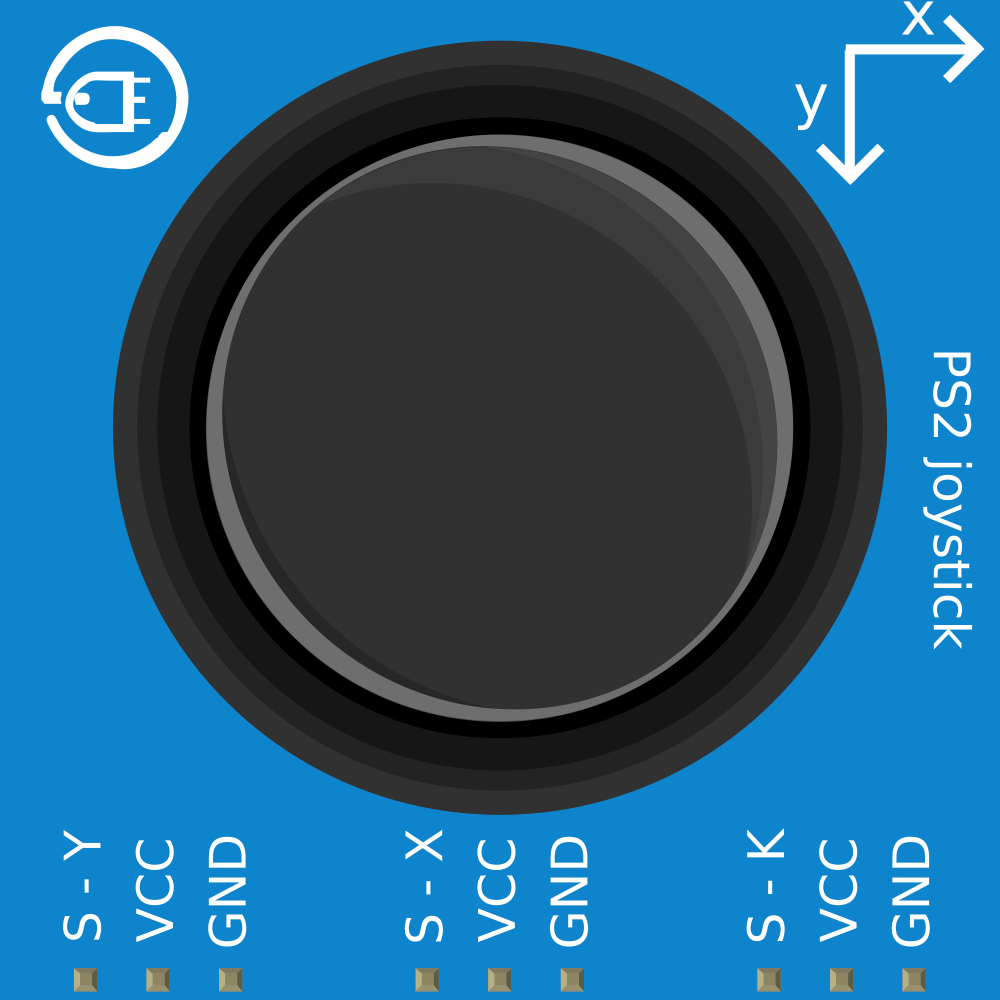
Pin Configuration and Descriptions

Pin Name Description
GND Ground connection
+5V Power supply (3.3V to 5V)
VRx Horizontal (X-axis) analog output
VRy Vertical (Y-axis) analog output
SW Push-button switch output

Usage Instructions

How to Use the Component in a Circuit

  1. Power Connections: Connect the +5V and GND pins to the power supply of your circuit, ensuring that it matches the voltage requirements of the joystick module.
  2. Analog Outputs: Connect the VRx and VRy pins to the analog input pins of your microcontroller to read the joystick's position.
  3. Button Connection: Connect the SW pin to a digital input pin on your microcontroller. You may need to use a pull-up resistor to ensure a stable high signal when the button is not pressed.

Important Considerations and Best Practices

  • Power Supply: Do not exceed the voltage rating as it may damage the potentiometers.
  • Calibration: Perform calibration for the analog outputs to ensure accurate position readings.
  • Debouncing: Implement software debouncing for the button press to avoid false triggering due to mechanical vibrations.
  • Mounting: Secure the joystick module to prevent movement during operation, which could lead to erroneous readings.

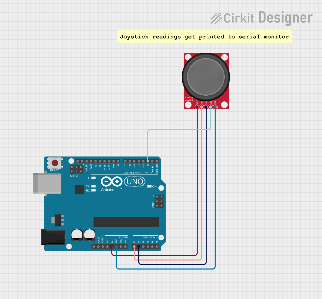
Example Code for Arduino UNO

// Define the Arduino analog pins connected to the joystick
const int xAxisPin = A0;
const int yAxisPin = A1;
const int buttonPin = 2; // Digital pin connected to the joystick button

void setup() {
  pinMode(xAxisPin, INPUT);
  pinMode(yAxisPin, INPUT);
  pinMode(buttonPin, INPUT_PULLUP); // Enable internal pull-up resistor
  Serial.begin(9600);
}

void loop() {
  // Read the joystick position values
  int xPosition = analogRead(xAxisPin);
  int yPosition = analogRead(yAxisPin);
  // Read the button state (LOW when pressed due to pull-up resistor)
  bool buttonState = !digitalRead(buttonPin);

  // Print the values to the Serial Monitor
  Serial.print("X: ");
  Serial.print(xPosition);
  Serial.print(" | Y: ");
  Serial.print(yPosition);
  Serial.print(" | Button: ");
  Serial.println(buttonState ? "Pressed" : "Released");

  delay(100); // Short delay for readability
}

Troubleshooting and FAQs

Common Issues Users Might Face

  • Inaccurate Readings: If the joystick provides inconsistent readings, ensure that the power supply is stable and within the specified voltage range. Also, recalibrate the joystick's center position in your software.
  • Button Not Responding: Check the button connections and ensure that the pull-up resistor is enabled. If using an external resistor, verify that it is properly connected.
  • Intermittent Connectivity: Loose connections can cause intermittent behavior. Ensure all pins are securely connected to the microcontroller.

Solutions and Tips for Troubleshooting

  • Calibration: Use a calibration sketch to map the joystick's full range of motion and set the center position.
  • Debouncing: Implement a software debounce routine to filter out spurious button presses.
  • Connection Check: Re-seat all connections and inspect for any potential solder joint issues.

FAQs

Q: Can I use the PS2 Joystick with a 3.3V system? A: Yes, the PS2 Joystick can typically operate at 3.3V, but the analog range will be reduced.

Q: How can I increase the precision of the joystick readings? A: Use the analogReference() function in Arduino to set a different voltage reference, or add an external ADC with higher resolution.

Q: What should I do if the joystick drifts from the center position? A: Implement a dead zone in your code where small deviations from the center are ignored, or recalibrate the center position.

Q: Is it necessary to use an external pull-up resistor for the button? A: No, if you are using an Arduino, you can use the internal pull-up resistor by setting the button pin mode to INPUT_PULLUP.

This documentation provides a comprehensive guide to integrating and using the PS2 Joystick module in your electronic projects. For further assistance or advanced applications, consult the community forums or technical resources specific to your microcontroller platform.