How to Use A4988 Stepper Motor Driver (Red): Examples, Pinouts, and Specs
Introduction
The A4988 Stepper Motor Driver is a compact driver module that is widely used to control bipolar stepper motors. It is particularly popular in the fields of 3D printing and CNC machining due to its ability to provide precise control over motor movement through microstepping. The driver is capable of driving a single stepper motor and offers adjustable current limiting, overcurrent protection, and five different step resolutions.
Explore Projects Built with A4988 Stepper Motor Driver (Red)

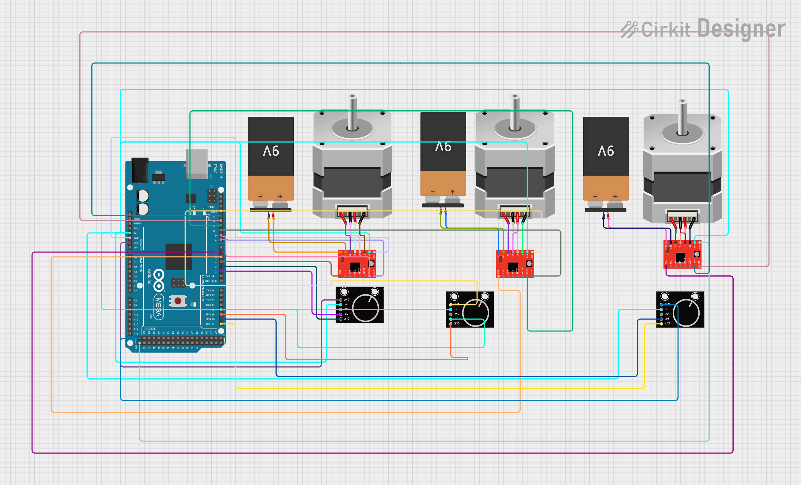
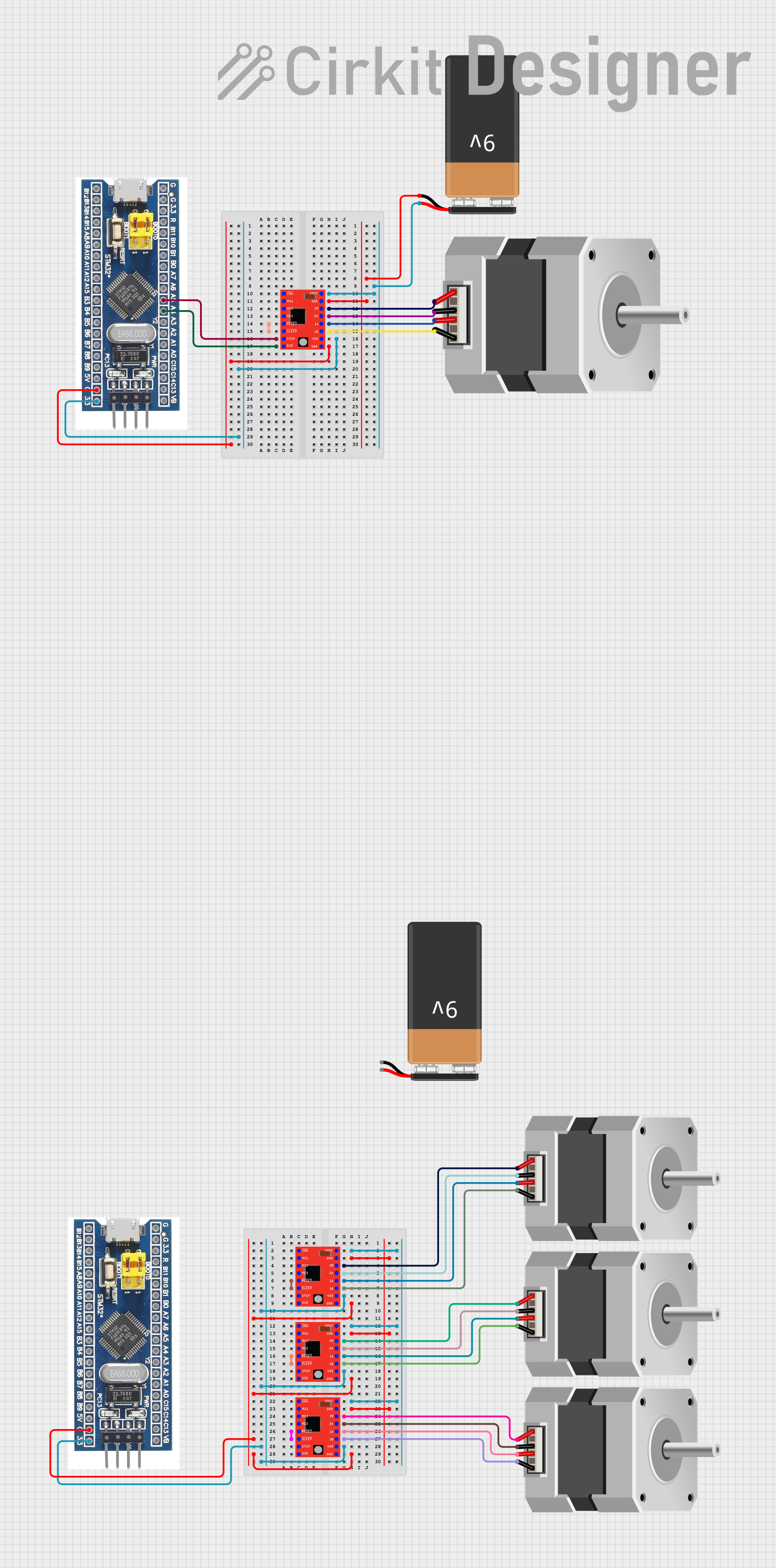
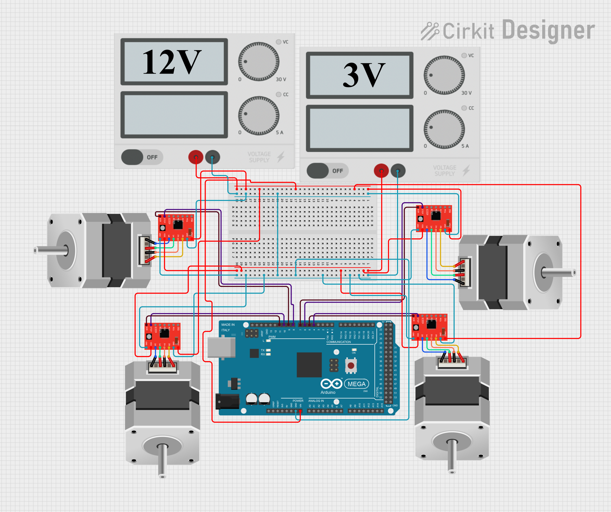
Explore Projects Built with A4988 Stepper Motor Driver (Red)
Common Applications and Use Cases
- 3D Printers
- CNC Machines
- Precise positioning in robotics
- Automated equipment and machinery
Technical Specifications
Key Technical Details
- Logic Voltage (VDD): 3.3 - 5.5 V
- Motor Supply Voltage (VMOT): 8 - 35 V
- Output Current (per channel): Up to 2 A (with proper heat sinking)
- Microstep Resolutions: Full, 1/2, 1/4, 1/8, 1/16
- Thermal Overload Protection: Yes
- Under-voltage Lockout: Yes
- Crossover-current Protection: Yes
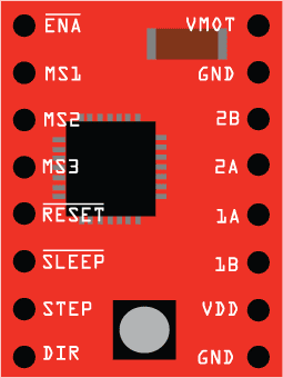
Pin Configuration and Descriptions
| Pin Number | Name | Description |
|---|---|---|
| 1 | VMOT | Motor supply voltage (8-35 V) |
| 2 | GND | Ground (0 V) |
| 3 | 2B | Motor coil B output 2 |
| 4 | 2A | Motor coil A output 2 |
| 5 | 1A | Motor coil A output 1 |
| 6 | 1B | Motor coil B output 1 |
| 7 | VDD | Logic supply voltage (3.3-5.5 V) |
| 8 | GND | Ground (0 V) for logic |
| 9 | ENABLE | Logic input to enable the driver (active low) |
| 10 | MS1 | Microstep selection 1 |
| 11 | MS2 | Microstep selection 2 |
| 12 | MS3 | Microstep selection 3 |
| 13 | RESET | Logic input to reset the driver (active low) |
| 14 | SLEEP | Logic input to put the driver in sleep mode (active low) |
| 15 | STEP | Logic input to take a step when pulsed |
| 16 | DIR | Logic input to select motor direction |
Usage Instructions
How to Use the Component in a Circuit
Power Supply: Connect the motor power supply to the VMOT and GND pins, ensuring that the voltage is within the specified range (8-35 V). Connect the logic power supply to the VDD and GND pins, ensuring that the voltage is within the specified range (3.3-5.5 V).
Motor Connection: Connect the stepper motor coils to the A4988 outputs (1A, 1B, 2A, 2B).
Microstepping Configuration: Set the MS1, MS2, and MS3 pins to high or low according to the desired microstepping resolution.
Control Inputs: Connect the STEP and DIR pins to the appropriate control signals from a microcontroller or other control circuitry. The ENABLE pin can be used to turn the motor output on and off.
Important Considerations and Best Practices
- Always ensure that the power supply is disconnected when making connections to the A4988 driver.
- Use proper decoupling capacitors close to the VMOT and VDD pins to minimize voltage spikes.
- Avoid connecting or disconnecting a motor while the driver is powered to prevent damage.
- Heat sinking is recommended when running the driver near its maximum current rating.
- Adjust the current limiting potentiometer to match the current requirements of your stepper motor.
Troubleshooting and FAQs
Common Issues Users Might Face
- Motor not moving: Check power supply connections, ensure that the motor is properly connected, and verify that the STEP and DIR signals are being sent correctly.
- Overheating: Ensure that the current limit is set correctly and that adequate heat sinking is in place.
- Erratic movement: Verify microstep configuration and check for any loose connections or shorts.
Solutions and Tips for Troubleshooting
- If the motor does not move, double-check all connections and measure voltages to ensure that the driver is powered correctly.
- For overheating issues, reduce the current limit, improve heat sinking, or add active cooling.
- Erratic movement can often be resolved by ensuring that the microstep settings are correct and that the control signals are clean and free of noise.
Example Code for Arduino UNO
// Define the connections to the A4988
const int dirPin = 2;  // DIR pin connected to digital pin 2
const int stepPin = 3; // STEP pin connected to digital pin 3

void setup() {
  // Set the pin modes for the DIR and STEP pins
  pinMode(dirPin, OUTPUT);
  pinMode(stepPin, OUTPUT);
}

void loop() {
  // Set the direction of the motor
  digitalWrite(dirPin, HIGH); // Set to HIGH to move in one direction

  // Move the motor one step
  digitalWrite(stepPin, HIGH);
  delayMicroseconds(1000); // This delay controls the speed
  digitalWrite(stepPin, LOW);
  delayMicroseconds(1000);
}
Note: The above code is a simple example to move the stepper motor in one direction at a constant speed. Adjust the delay to control the speed of the motor. The direction can be changed by setting the dirPin to LOW.