
How to Use WisNode Bridge IO Lite_4 Digital Output: Examples, Pinouts, and Specs
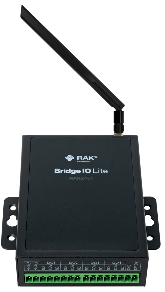
 Design with WisNode Bridge IO Lite_4 Digital Output in Cirkit Designer
Introduction
The WisNode Bridge IO Lite_4 Digital Output (RAK2461) is a versatile digital output module designed by RAK. It is an expansion module for the WisNode Bridge, enabling control of up to four digital outputs. This module is ideal for applications in automation, IoT projects, and remote control systems. With its compact design and reliable performance, the RAK2461 simplifies the process of integrating digital outputs into your projects.
Explore Projects Built with WisNode Bridge IO Lite_4 Digital Output
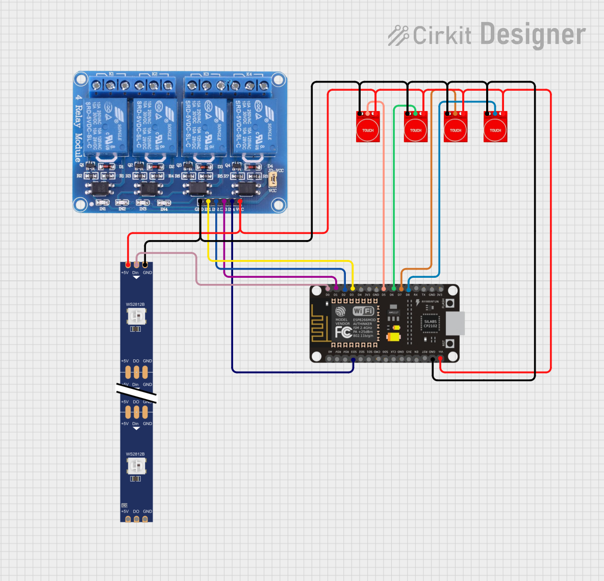 Open Project in Cirkit Designer
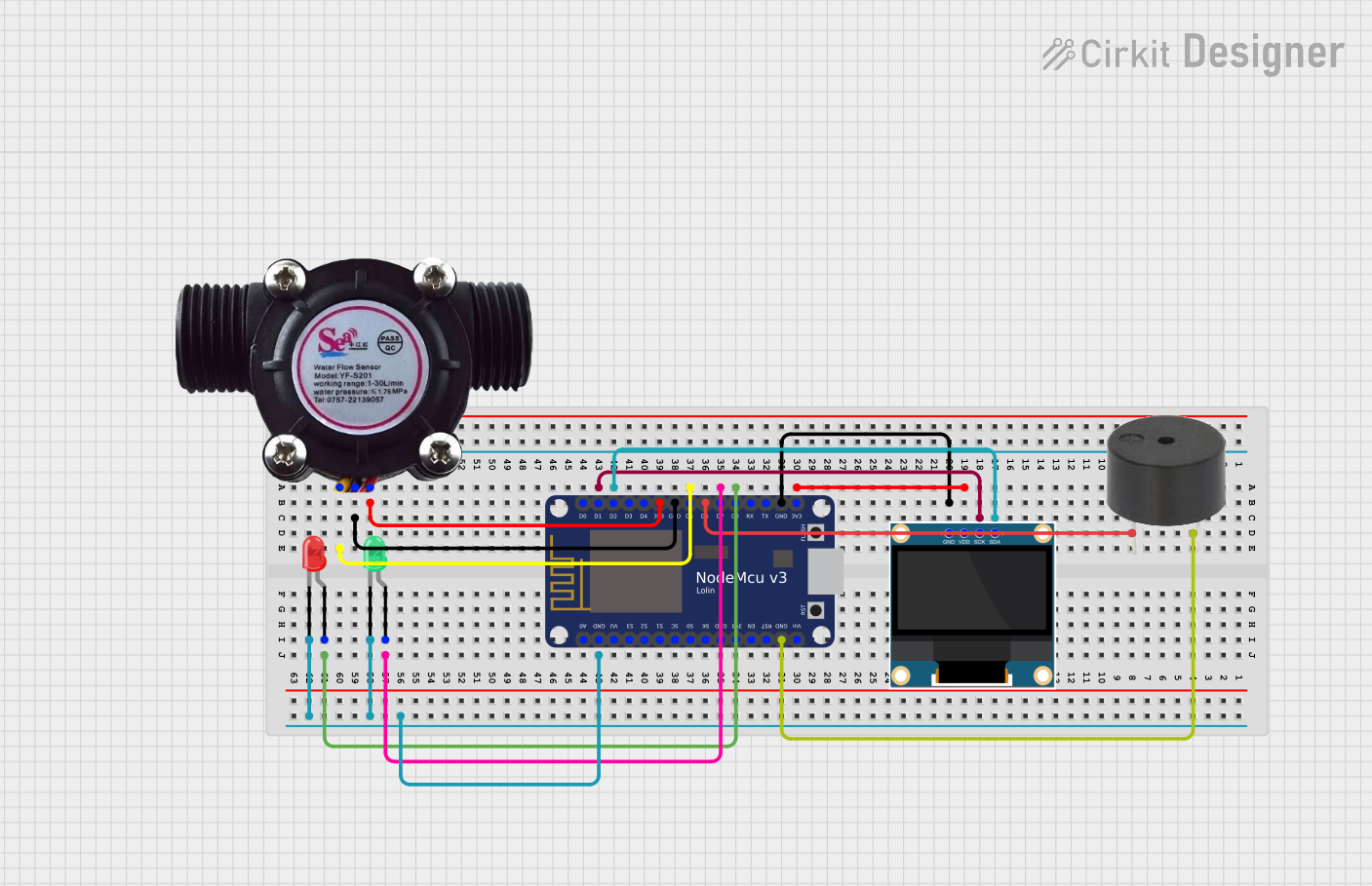 Open Project in Cirkit Designer
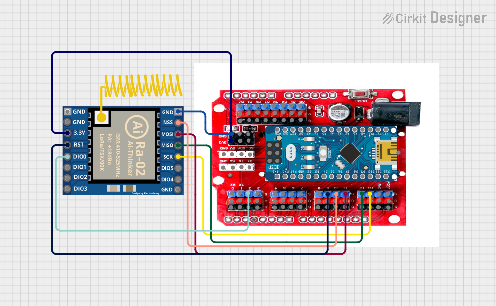 Open Project in Cirkit Designer
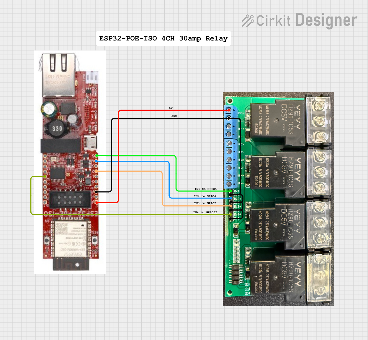 Open Project in Cirkit Designer
Explore Projects Built with WisNode Bridge IO Lite_4 Digital Output
Open Project in Cirkit DesignerOpen Project in Cirkit DesignerOpen Project in Cirkit DesignerOpen Project in Cirkit DesignerCommon Applications and Use Cases
- Home automation (e.g., controlling lights, fans, or appliances)
- Industrial automation (e.g., activating relays or solenoids)
- IoT systems requiring remote control of devices
- Smart agriculture (e.g., controlling irrigation systems)
- Robotics and motor control
Technical Specifications
The following table outlines the key technical specifications of the RAK2461 module:
| Parameter | Value |
|---|---|
| Operating Voltage | 5V DC |
| Output Voltage Range | 0V to 5V DC |
| Maximum Output Current | 500mA per channel |
| Number of Outputs | 4 |
| Communication Interface | UART (via WisNode Bridge) |
| Dimensions | 50mm x 25mm x 10mm |
| Operating Temperature | -40°C to 85°C |
Pin Configuration and Descriptions
The RAK2461 module has a simple pinout for connecting to the WisNode Bridge. Below is the pin configuration:
| Pin Name | Description |
|---|---|
| VCC | Power supply input (5V DC) |
| GND | Ground |
| TX | UART Transmit (to WisNode Bridge RX) |
| RX | UART Receive (from WisNode Bridge TX) |
| OUT1 | Digital Output 1 |
| OUT2 | Digital Output 2 |
| OUT3 | Digital Output 3 |
| OUT4 | Digital Output 4 |
Usage Instructions
How to Use the Component in a Circuit
- Power the Module: Connect the
VCCpin to a 5V DC power source and theGNDpin to ground. - Connect to WisNode Bridge: Use the
TXandRXpins to establish UART communication with the WisNode Bridge. - Connect Outputs: Attach the devices you want to control (e.g., LEDs, relays, or motors) to the
OUT1,OUT2,OUT3, andOUT4pins. Ensure the connected devices do not exceed the maximum output current of 500mA per channel. - Control Outputs: Use the WisNode Bridge to send UART commands to toggle the digital outputs.
Important Considerations and Best Practices
- Power Supply: Ensure a stable 5V DC power supply to avoid damage to the module or connected devices.
- Output Current: Do not exceed the 500mA current limit per channel. Use external relays or transistors for higher current loads.
- UART Configuration: Configure the UART communication parameters (baud rate, parity, etc.) as specified in the WisNode Bridge documentation.
- Isolation: For inductive loads (e.g., motors or solenoids), use flyback diodes to protect the module from voltage spikes.
Example Code for Arduino UNO
The following example demonstrates how to control the RAK2461 module using an Arduino UNO. This code assumes the module is connected to the Arduino's hardware UART pins (TX and RX).
// Example code to control RAK2461 digital outputs using Arduino UNO
// Ensure the RAK2461 TX is connected to Arduino RX (pin 0)
// and RAK2461 RX is connected to Arduino TX (pin 1).

void setup() {
  Serial.begin(9600); // Initialize UART communication at 9600 baud
  delay(1000);        // Wait for the module to initialize
}

void loop() {
  // Turn ON Output 1
  Serial.println("OUT1 ON"); // Send command to turn ON Output 1
  delay(1000);               // Wait for 1 second

  // Turn OFF Output 1
  Serial.println("OUT1 OFF"); // Send command to turn OFF Output 1
  delay(1000);                // Wait for 1 second

  // Repeat for other outputs as needed
}
Note: Replace "OUT1 ON" and "OUT1 OFF" with the actual UART commands required by the WisNode Bridge to control the outputs. Refer to the WisNode Bridge documentation for the exact command format.
Troubleshooting and FAQs
Common Issues Users Might Face
No Response from the Module
- Cause: Incorrect UART connection or configuration.
- Solution: Verify the TX and RX connections. Ensure the baud rate matches the WisNode Bridge settings.
Output Not Activating
- Cause: Exceeding the maximum output current or incorrect wiring.
- Solution: Check the connected load and ensure it is within the 500mA limit. Verify the wiring.
Module Overheating
- Cause: Overloading the outputs or insufficient ventilation.
- Solution: Reduce the load on the outputs and ensure proper airflow around the module.
Interference with Other Devices
- Cause: Inductive loads causing voltage spikes.
- Solution: Use flyback diodes or snubber circuits for inductive loads.
Solutions and Tips for Troubleshooting
- Use a multimeter to verify the output voltage and current.
- Test the module with a simple load (e.g., an LED with a resistor) to confirm basic functionality.
- Double-check all connections and ensure proper grounding.
- Refer to the WisNode Bridge documentation for detailed UART command syntax and examples.
By following this documentation, you can effectively integrate the WisNode Bridge IO Lite_4 Digital Output (RAK2461) into your projects and troubleshoot any issues that arise.