How to Use D1 Mini ESP32: Examples, Pinouts, and Specs
Introduction
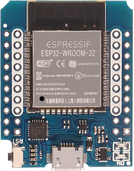
The D1 Mini ESP32, manufactured by AZDelivery, is a compact and versatile development board based on the powerful ESP32 chip. It combines Wi-Fi and Bluetooth capabilities, making it ideal for IoT (Internet of Things) applications. The board features a USB interface for programming and power, as well as multiple GPIO pins for connecting sensors, actuators, and other peripherals. Its small form factor and compatibility with the Arduino IDE make it a popular choice for both beginners and experienced developers.
Explore Projects Built with D1 Mini ESP32

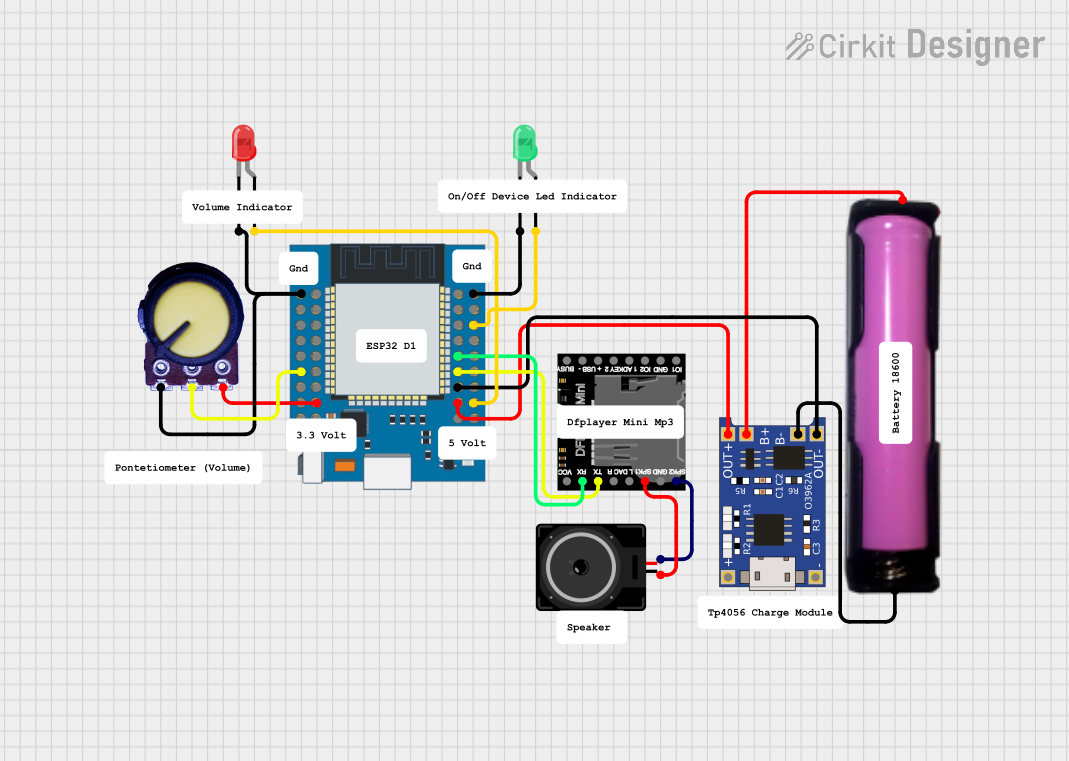
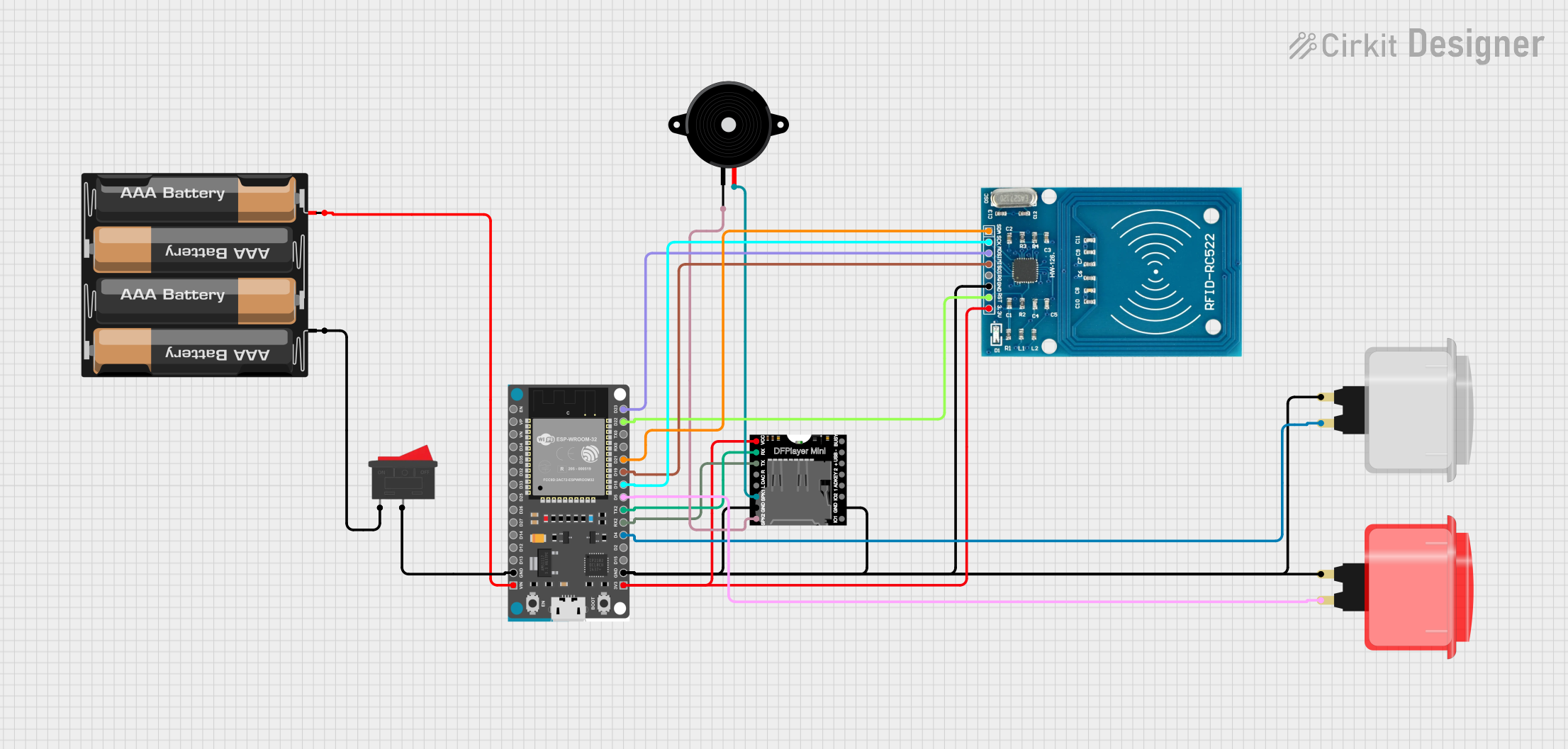

Explore Projects Built with D1 Mini ESP32
Common Applications and Use Cases
- Home automation systems
- Wireless sensor networks
- IoT devices and prototypes
- Remote monitoring and control
- Bluetooth-enabled projects
- Smart appliances and wearables
Technical Specifications
The D1 Mini ESP32 is designed to provide robust performance in a compact package. Below are its key technical details:
General Specifications
| Parameter | Value |
|---|---|
| Microcontroller | ESP32 (dual-core, Xtensa LX6) |
| Clock Speed | Up to 240 MHz |
| Flash Memory | 4 MB |
| SRAM | 520 KB |
| Wi-Fi | 802.11 b/g/n |
| Bluetooth | v4.2 BR/EDR and BLE |
| Operating Voltage | 3.3V |
| Input Voltage (USB) | 5V |
| GPIO Pins | 11 |
| Dimensions | 34.2 mm x 25.6 mm |
Pin Configuration and Descriptions
The D1 Mini ESP32 features a total of 16 pins, including power, ground, and GPIO pins. Below is the pinout and description:
| Pin Name | Function | Description |
|---|---|---|
| 3V3 | Power Output | Provides 3.3V output for external components. |
| GND | Ground | Common ground for the circuit. |
| D0 | GPIO16 | General-purpose I/O pin. |
| D1 | GPIO5 | General-purpose I/O pin. |
| D2 | GPIO4 | General-purpose I/O pin. |
| D3 | GPIO0 | General-purpose I/O pin. |
| D4 | GPIO2 | General-purpose I/O pin. |
| D5 | GPIO14 | General-purpose I/O pin. |
| D6 | GPIO12 | General-purpose I/O pin. |
| D7 | GPIO13 | General-purpose I/O pin. |
| D8 | GPIO15 | General-purpose I/O pin. |
| RX | GPIO3 (UART RX) | UART receive pin for serial communication. |
| TX | GPIO1 (UART TX) | UART transmit pin for serial communication. |
| A0 | Analog Input (ADC) | Reads analog signals (0-3.3V). |
| EN | Enable | Enables or disables the chip. |
| RST | Reset | Resets the microcontroller. |
Usage Instructions
The D1 Mini ESP32 is easy to use and can be programmed using the Arduino IDE. Below are the steps to get started and important considerations:
Getting Started
Install the ESP32 Board Package in Arduino IDE:
- Open the Arduino IDE and go to
File > Preferences. - In the "Additional Board Manager URLs" field, add the following URL:
https://dl.espressif.com/dl/package_esp32_index.json - Go to
Tools > Board > Boards Manager, search for "ESP32," and install the package.
- Open the Arduino IDE and go to
Connect the D1 Mini ESP32 to Your Computer:
- Use a micro-USB cable to connect the board to your computer.
- Ensure the correct COM port is selected in the Arduino IDE (
Tools > Port).
Select the Board:
- In the Arduino IDE, go to
Tools > Boardand selectESP32 Dev Module.
- In the Arduino IDE, go to
Write and Upload Code:
- Write your code in the Arduino IDE and click the upload button to flash it to the board.
Example Code: Blink an LED
The following example demonstrates how to blink an LED connected to GPIO2 (D4):
// Define the GPIO pin for the LED
const int ledPin = 2; // GPIO2 corresponds to D4 on the D1 Mini ESP32

void setup() {
  pinMode(ledPin, OUTPUT); // Set the LED pin as an output
}

void loop() {
  digitalWrite(ledPin, HIGH); // Turn the LED on
  delay(1000);                // Wait for 1 second
  digitalWrite(ledPin, LOW);  // Turn the LED off
  delay(1000);                // Wait for 1 second
}
Important Considerations
- Power Supply: The D1 Mini ESP32 operates at 3.3V. Avoid applying higher voltages to the GPIO pins.
- GPIO Limitations: Some GPIO pins have specific functions or limitations (e.g., GPIO0 is used for boot mode).
- Wi-Fi and Bluetooth: Using both Wi-Fi and Bluetooth simultaneously may increase power consumption.
- External Components: Use appropriate resistors, capacitors, or level shifters when connecting external devices.
Troubleshooting and FAQs
Common Issues and Solutions
The board is not detected by the Arduino IDE:
- Ensure the correct USB driver is installed (e.g., CP210x or CH340 driver).
- Check the USB cable and port for proper connection.
Upload fails with a timeout error:
- Press and hold the
BOOTbutton on the board while uploading the code. - Ensure the correct COM port and board are selected in the Arduino IDE.
- Press and hold the
Wi-Fi connection issues:
- Verify the SSID and password in your code.
- Ensure the router is within range and supports 2.4 GHz Wi-Fi.
The board overheats:
- Avoid overloading the GPIO pins or using the board in high-temperature environments.
- Ensure proper ventilation during operation.
FAQs
Q: Can I power the D1 Mini ESP32 with a battery?
A: Yes, you can power the board using a 3.7V LiPo battery connected to the 3V3 and GND pins. However, ensure the battery voltage is regulated to 3.3V.
Q: Is the D1 Mini ESP32 compatible with ESP8266 libraries?
A: No, the ESP32 has a different architecture and requires libraries specifically designed for ESP32.
Q: How do I reset the board?
A: Press the RST button on the board to perform a hardware reset.
Q: Can I use the D1 Mini ESP32 for deep sleep?
A: Yes, the ESP32 supports deep sleep mode for low-power applications. Use the esp_deep_sleep() function in your code.
By following this documentation, you can effectively use the D1 Mini ESP32 for a wide range of projects and applications.