How to Use 1CH Optocoupler PC817 1 Channel Isolation Board: Examples, Pinouts, and Specs
1CH Optocoupler PC817 1 Channel Isolation Board Documentation
Introduction
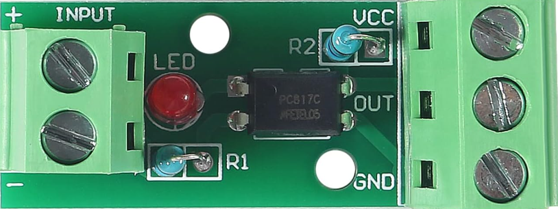
The PC817 1 Channel Isolation Board is a compact and versatile module designed to provide electrical isolation between input and output signals. At its core, the board uses the PC817 optocoupler, which consists of an internal LED and a phototransistor. When a signal is applied to the input, the LED emits light, which is detected by the phototransistor, enabling signal transmission without direct electrical connection.
This isolation mechanism is crucial for protecting sensitive components from high voltages, noise, or ground loops. The module is widely used in applications such as:
- Microcontroller interfacing: Safely connecting microcontrollers (e.g., Arduino, Raspberry Pi) to high-voltage circuits.
- Signal isolation: Preventing electrical interference between different parts of a circuit.
- Voltage level shifting: Interfacing between circuits operating at different voltage levels.
- Industrial automation: Isolating control signals in industrial equipment.
Technical Specifications
The following table outlines the key technical details of the PC817 1 Channel Isolation Board:
| Parameter | Value |
|---|---|
| Input Voltage (Vcc) | 3.3V to 5V |
| Input Current | 5mA to 20mA (typical) |
| Output Voltage | 0V to 30V (max) |
| Output Current | 50mA (max) |
| Isolation Voltage | 5kV (between input and output) |
| Response Time | 2µs to 4µs |
| Operating Temperature | -30°C to +100°C |
| Dimensions | 25mm x 15mm x 10mm |
Pin Configuration
The PC817 1 Channel Isolation Board has four pins, as described in the table below:
| Pin | Name | Description |
|---|---|---|
| 1 | VCC | Positive input voltage (3.3V to 5V). Powers the internal LED of the optocoupler. |
| 2 | GND | Ground connection for the input side. |
| 3 | OUT | Output signal pin. Connects to the collector of the phototransistor. |
| 4 | GND (Output) | Ground connection for the output side. |
Usage Instructions
How to Use the PC817 1 Channel Isolation Board in a Circuit
Power the Input Side:
- Connect the VCC pin to a 3.3V or 5V power source.
- Connect the GND pin to the ground of the input circuit.
Connect the Output Side:
- Connect the OUT pin to the input of the circuit you want to control or isolate.
- Connect the GND (Output) pin to the ground of the output circuit.
Signal Transmission:
- When a voltage is applied to the input side (VCC), the internal LED emits light, activating the phototransistor on the output side. This allows the signal to pass through while maintaining electrical isolation.
Important Considerations and Best Practices
- Input Current Limiting: Use a current-limiting resistor on the input side to prevent excessive current through the internal LED. For example, with a 5V input, a 220Ω resistor is recommended.
- Output Pull-Up Resistor: If the output is connected to a digital input pin of a microcontroller, use a pull-up resistor (e.g., 10kΩ) to ensure a stable HIGH signal when the optocoupler is off.
- Voltage Compatibility: Ensure the output voltage and current do not exceed the maximum ratings of the optocoupler.
- Avoid High-Frequency Signals: The PC817 is not suitable for high-speed signal transmission due to its response time (2µs to 4µs).
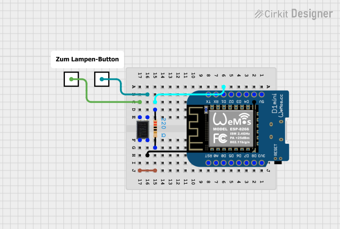
Example Circuit with Arduino UNO
Below is an example of how to use the PC817 1 Channel Isolation Board with an Arduino UNO to control an LED:
Circuit Diagram
- Input Side:
- VCC → Arduino 5V
- GND → Arduino GND
- Signal Input → Arduino Digital Pin 7 (with a 220Ω resistor)
- Output Side:
- OUT → LED (with a 330Ω resistor) → GND (Output)
Arduino Code
// Define the input and output pins
const int inputPin = 7;  // Arduino pin connected to the optocoupler input
const int ledPin = 13;   // Arduino built-in LED pin (or external LED)

void setup() {
  pinMode(inputPin, OUTPUT); // Set the input pin as an output
  pinMode(ledPin, OUTPUT);   // Set the LED pin as an output
}

void loop() {
  digitalWrite(inputPin, HIGH); // Turn on the optocoupler input
  delay(1000);                  // Wait for 1 second
  digitalWrite(inputPin, LOW);  // Turn off the optocoupler input
  delay(1000);                  // Wait for 1 second
}
Explanation of the Code
- The Arduino sends a HIGH signal to the optocoupler input pin, turning on the internal LED.
- This activates the phototransistor, allowing current to flow through the output side and lighting up the external LED.
- The process repeats every second, demonstrating the isolation and signal transmission capabilities of the PC817.
Troubleshooting and FAQs
Common Issues and Solutions
| Issue | Possible Cause | Solution |
|---|---|---|
| Output signal not working | Incorrect wiring or missing pull-up resistor | Double-check connections and add a pull-up resistor to the output pin. |
| Optocoupler overheating | Excessive input current | Use a current-limiting resistor on the input side (e.g., 220Ω for 5V input). |
| Slow response or signal distortion | High-frequency input signal | Use the PC817 only for low-frequency signals (below 10kHz). |
| No isolation between input and output | Ground loops between input and output sides | Ensure the input and output grounds are electrically isolated. |
FAQs
Can the PC817 handle AC signals?
- Yes, but only low-frequency AC signals. For AC signals, ensure proper rectification and current limiting.
What is the maximum voltage the output can handle?
- The output can handle up to 30V, but the current should not exceed 50mA.
Can I use the PC817 with a 3.3V microcontroller?
- Yes, the PC817 works with 3.3V logic levels. Ensure the input current is sufficient to activate the internal LED.
Why is the output signal inverted?
- The PC817 operates as an inverting optocoupler. When the input is HIGH, the output is LOW, and vice versa.
Conclusion
The PC817 1 Channel Isolation Board is a reliable and cost-effective solution for signal isolation and voltage level shifting. Its simple design and robust performance make it an essential component for protecting sensitive electronics and ensuring safe interfacing between circuits. By following the guidelines and examples provided in this documentation, users can effectively integrate the PC817 into their projects.
Explore Projects Built with 1CH Optocoupler PC817 1 Channel Isolation Board


Explore Projects Built with 1CH Optocoupler PC817 1 Channel Isolation Board