How to Use Power Module: Examples, Pinouts, and Specs
Introduction
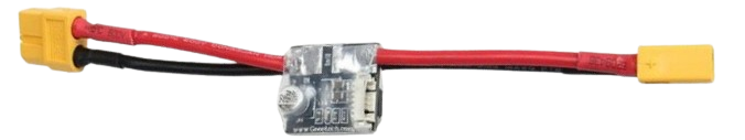
The Holybro PX4 PM Power Module is a compact and efficient device designed to provide regulated electrical power to electronic circuits. It integrates voltage regulation and protection features, ensuring stable and safe operation for connected components. This module is particularly suited for use in drone systems, robotics, and other embedded applications where reliable power delivery is critical.
Explore Projects Built with Power Module


Explore Projects Built with Power Module
Common Applications and Use Cases
- Powering flight controllers in drones and UAVs
- Supplying regulated power to embedded systems and microcontrollers
- Monitoring battery voltage and current in real-time
- Providing overcurrent and overvoltage protection in sensitive circuits
Technical Specifications
The following table outlines the key technical details of the Holybro PX4 PM Power Module:
| Parameter | Value |
|---|---|
| Input Voltage Range | 4.5V to 10V |
| Output Voltage | 5.35V ± 0.1V (regulated) |
| Maximum Current Output | 3A |
| Voltage Measurement Range | 0V to 60V |
| Current Measurement Range | 0A to 120A |
| Connector Type | XT60 for input/output, 6-pin JST-GH for FC |
| Dimensions | 25mm x 21mm x 9mm |
| Weight | 20g |
Pin Configuration and Descriptions
The Holybro PX4 PM Power Module features a 6-pin JST-GH connector for interfacing with flight controllers or other devices. The pinout is as follows:
| Pin Number | Pin Name | Description |
|---|---|---|
| 1 | VCC | Regulated 5.35V output |
| 2 | GND | Ground |
| 3 | Voltage | Battery voltage sense (scaled) |
| 4 | Current | Battery current sense (scaled) |
| 5 | NC | Not connected |
| 6 | NC | Not connected |
Usage Instructions
How to Use the Power Module in a Circuit
Connect the Input Power Source:
- Use the XT60 connector to connect the power module to a battery or other DC power source. Ensure the input voltage is within the specified range (4.5V to 10V).
Connect the Output to the Load:
- Use the XT60 output connector to supply power to your load (e.g., motors, flight controller, or other devices).
Interface with a Flight Controller:
- Use the 6-pin JST-GH cable to connect the power module to the flight controller. This allows the flight controller to monitor battery voltage and current.
Secure the Module:
- Mount the power module securely in your system to prevent vibrations or loose connections.
Important Considerations and Best Practices
- Voltage and Current Limits: Ensure the connected load does not exceed the maximum current output of 3A.
- Heat Dissipation: Avoid placing the module in enclosed spaces without ventilation, as it may generate heat during operation.
- Polarity: Double-check the polarity of all connections to prevent damage to the module or connected devices.
- Battery Monitoring: Use the voltage and current sense pins to monitor battery health and prevent over-discharge.
Example: Connecting to an Arduino UNO
The Holybro PX4 PM Power Module can be used to power an Arduino UNO and monitor battery voltage and current. Below is an example Arduino sketch for reading the voltage and current values:
// Example code for reading voltage and current from the Holybro PX4 PM Power Module
// Connect the Voltage pin to A0 and the Current pin to A1 on the Arduino UNO

const int voltagePin = A0; // Pin connected to the Voltage sense output
const int currentPin = A1; // Pin connected to the Current sense output

// Voltage and current scaling factors (adjust based on module specifications)
const float voltageScale = 0.017; // Scale factor for voltage (V per ADC unit)
const float currentScale = 0.037; // Scale factor for current (A per ADC unit)

void setup() {
  Serial.begin(9600); // Initialize serial communication
  pinMode(voltagePin, INPUT);
  pinMode(currentPin, INPUT);
}

void loop() {
  // Read raw ADC values
  int rawVoltage = analogRead(voltagePin);
  int rawCurrent = analogRead(currentPin);

  // Convert raw values to actual voltage and current
  float batteryVoltage = rawVoltage * voltageScale;
  float batteryCurrent = rawCurrent * currentScale;

  // Print the results to the Serial Monitor
  Serial.print("Battery Voltage: ");
  Serial.print(batteryVoltage);
  Serial.println(" V");

  Serial.print("Battery Current: ");
  Serial.print(batteryCurrent);
  Serial.println(" A");

  delay(1000); // Wait for 1 second before the next reading
}
Troubleshooting and FAQs
Common Issues and Solutions
No Output Voltage:
- Cause: Input power source is not connected or is below the minimum voltage.
- Solution: Verify the input power source and ensure it is within the 4.5V to 10V range.
Overheating:
- Cause: Excessive current draw or poor ventilation.
- Solution: Ensure the load does not exceed 3A and provide adequate airflow around the module.
Incorrect Voltage or Current Readings:
- Cause: Improper scaling factors in the monitoring system.
- Solution: Verify and adjust the scaling factors in your code or monitoring device.
Loose Connections:
- Cause: Vibrations or improper mounting.
- Solution: Secure all connections and mount the module firmly in your system.
FAQs
Q: Can the module handle voltages above 10V?
A: No, the input voltage must remain within the 4.5V to 10V range to avoid damaging the module.
Q: Is the module compatible with other flight controllers besides PX4?
A: Yes, the module can be used with other flight controllers that support voltage and current sensing via a 6-pin JST-GH connector.
Q: Can I use this module to power multiple devices?
A: Yes, as long as the total current draw does not exceed 3A.
Q: How do I calibrate the voltage and current readings?
A: Use a multimeter to measure the actual voltage and current, then adjust the scaling factors in your code to match the readings.
This concludes the documentation for the Holybro PX4 PM Power Module.