
How to Use USB Connectors: Examples, Pinouts, and Specs
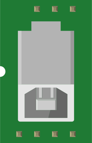
 Design with USB Connectors in Cirkit Designer
Introduction
USB connectors, such as the SparkFun USB-MB-H, are standardized interfaces designed for connecting electronic devices to computers, power sources, or other peripherals. They facilitate data transfer, device communication, and power delivery. These connectors are widely used in consumer electronics, embedded systems, and prototyping projects due to their versatility and ease of use.
Explore Projects Built with USB Connectors
 Open Project in Cirkit Designer
 Open Project in Cirkit Designer
 Open Project in Cirkit Designer
 Open Project in Cirkit Designer
Explore Projects Built with USB Connectors
Open Project in Cirkit DesignerOpen Project in Cirkit DesignerOpen Project in Cirkit DesignerOpen Project in Cirkit DesignerCommon Applications and Use Cases
- Data Transfer: Connecting devices like flash drives, external hard drives, and cameras to computers.
- Power Delivery: Charging smartphones, tablets, and other portable devices.
- Embedded Systems: Providing communication and power to microcontrollers and development boards.
- Prototyping: Used in DIY electronics projects for interfacing with USB-enabled devices.
Technical Specifications
The SparkFun USB-MB-H is a USB Micro-B connector, commonly used in modern electronics. Below are its key technical details:
Key Specifications
- Connector Type: USB Micro-B
- Manufacturer Part ID: USB-MB-H
- Voltage Rating: 5V DC (standard USB voltage)
- Current Rating: Up to 1.8A (depending on the application)
- Data Transfer Speed: Supports USB 2.0 (up to 480 Mbps)
- Mounting Style: Surface Mount Technology (SMT)
- Durability: Rated for 10,000 mating cycles
- Operating Temperature: -20°C to +85°C
Pin Configuration and Descriptions
The USB Micro-B connector has five pins, as detailed in the table below:
| Pin Number | Pin Name | Description |
|---|---|---|
| 1 | VBUS | Power supply (5V DC) |
| 2 | D- | Data line (negative) |
| 3 | D+ | Data line (positive) |
| 4 | ID | Identification pin (used in OTG devices) |
| 5 | GND | Ground |
Usage Instructions
How to Use the USB Connector in a Circuit
Mounting the Connector:
- The USB-MB-H is designed for surface mount applications. Ensure your PCB layout includes the appropriate footprint for this connector.
- Use solder paste and a reflow soldering process for secure mounting.
Connecting Power and Data Lines:
- Connect the VBUS pin to a 5V power source.
- Connect the D- and D+ pins to the corresponding data lines of your microcontroller or USB interface IC.
- Ensure the GND pin is connected to the ground plane of your circuit.
Using the ID Pin:
- For standard USB devices, leave the ID pin unconnected.
- For USB On-The-Go (OTG) applications, connect the ID pin to ground to configure the device as a host.
Testing the Connection:
- Verify the connections using a multimeter to ensure there are no shorts or open circuits.
- Plug in a USB cable and test the functionality of your circuit.
Important Considerations and Best Practices
- Power Supply: Ensure the power source can supply sufficient current for your application. Exceeding the current rating may damage the connector or connected devices.
- Signal Integrity: Keep the D- and D+ traces as short and direct as possible to minimize signal degradation.
- ESD Protection: Add ESD protection diodes to the data lines to protect against electrostatic discharge.
- Cable Selection: Use high-quality USB cables to ensure reliable data transfer and power delivery.
Example: Connecting to an Arduino UNO
The USB-MB-H connector can be used to interface with an Arduino UNO for power and serial communication. Below is an example of Arduino code for serial communication:
// Example: Serial Communication via USB
// This code sends a message to the serial monitor every second.

void setup() {
  Serial.begin(9600); // Initialize serial communication at 9600 baud
  while (!Serial) {
    // Wait for the serial port to connect (for boards like Leonardo)
  }
  Serial.println("USB Communication Initialized");
}

void loop() {
  Serial.println("Hello, USB!"); // Send a message to the serial monitor
  delay(1000); // Wait for 1 second
}
Troubleshooting and FAQs
Common Issues and Solutions
No Power to the Device:
- Cause: Incorrect connection of the VBUS or GND pins.
- Solution: Verify the power connections and ensure the power source is functioning.
Data Transfer Fails:
- Cause: Poor soldering or damaged data lines.
- Solution: Inspect the solder joints and ensure the D- and D+ lines are properly connected.
Device Not Recognized by Computer:
- Cause: Missing or incorrect drivers.
- Solution: Install the appropriate USB drivers for your device.
Overheating Connector:
- Cause: Excessive current draw.
- Solution: Check the current requirements of your device and ensure they are within the connector's rating.
FAQs
Q: Can the USB-MB-H connector be used for USB 3.0 applications?
A: No, the USB-MB-H is designed for USB 2.0 and does not support the additional pins required for USB 3.0.Q: How do I clean the connector if it gets dirty?
A: Use a soft brush and isopropyl alcohol to gently clean the connector. Avoid using excessive force.Q: Can I use this connector for charging high-power devices?
A: The USB-MB-H supports up to 1.8A. For higher power requirements, consider using a connector designed for USB Power Delivery (USB-PD).
This concludes the documentation for the SparkFun USB-MB-H connector.