Cirkit Designer Logo
Cirkit Designer
Your all-in-one circuit design IDE
Home / 
Component Documentation

How to Use FireBeetle 2 ESP32-E (N16R2) IoT Board: Examples, Pinouts, and Specs

Image of FireBeetle 2 ESP32-E (N16R2) IoT Board
Cirkit Designer LogoDesign with FireBeetle 2 ESP32-E (N16R2) IoT Board in Cirkit Designer

Introduction

The FireBeetle 2 ESP32-E (N16R2), manufactured by DFRobot, is a compact and powerful IoT development board based on the ESP32-E chip. It is designed for wireless communication and seamless integration with sensors, making it an excellent choice for building smart devices and IoT applications. The board supports dual-mode Bluetooth (BLE and Classic) and Wi-Fi, offering robust connectivity for a wide range of projects.

Explore Projects Built with FireBeetle 2 ESP32-E (N16R2) IoT Board

Use Cirkit Designer to design, explore, and prototype these projects online. Some projects support real-time simulation. Click "Open Project" to start designing instantly!
NUCLEO-F303RE and ESP8266 Based Air Quality Monitoring System with I2C LCD Display and Buzzer Alerts
Image of GAS LEAKAGE DETECTION: A project utilizing FireBeetle 2 ESP32-E (N16R2) IoT Board in a practical application
This circuit features a NUCLEO-F303RE microcontroller board interfaced with an ESP8266 ESP-01 WiFi module for wireless connectivity, an MQ-2 gas sensor for detecting combustible gases, a buzzer module for audible alerts, and an LCD display for visual feedback. The microcontroller communicates with the LCD via I2C and with the WiFi module via UART. The buzzer is driven by one of the microcontroller's timers, and the gas sensor's analog output is connected to an ADC pin on the microcontroller for gas concentration measurement.
Cirkit Designer LogoOpen Project in Cirkit Designer
ESP32-Based Environmental Monitoring System with NeoPixel Feedback and I2C Sensor Integration
Image of MSES: A project utilizing FireBeetle 2 ESP32-E (N16R2) IoT Board in a practical application
This circuit features an ESP32 microcontroller as the central processing unit, interfacing with a variety of sensors and peripherals. It includes an MQ-2 gas sensor, a BH1750 light sensor, multiple Adafruit NeoPixel LED sticks, a DHT22 temperature and humidity sensor, an IR transmitter, and piezo sensors. The ESP32 manages an I2C bus connecting the BH1750 and two LCD displays, controls a stepper motor via a driver module, reads analog signals from the MQ-2 sensor, and drives NeoPixel LEDs and the IR transmitter. The circuit appears to be designed for environmental monitoring and response with visual feedback and actuation capabilities.
Cirkit Designer LogoOpen Project in Cirkit Designer
ESP32-Based Multi-Sensor Monitoring System
Image of ESP32 SENSOR CONNECT: A project utilizing FireBeetle 2 ESP32-E (N16R2) IoT Board in a practical application
This circuit features an ESP32 microcontroller connected to various sensors: an MQ-2 gas sensor, a KY-038 sound sensor, a DHT22 temperature and humidity sensor, and an SHT113 flame sensor. The ESP32 reads analog signals from the MQ-2, KY-038, and SHT113 sensors, and digital signals from the MQ-2, KY-038, SHT113, and DHT22 sensors. Additionally, there is a red LED that can be controlled by the ESP32, likely for indicating status or alerts.
Cirkit Designer LogoOpen Project in Cirkit Designer
ESP32-Based Fire Alert System with LCD Display and Buzzer
Image of Fire Alert System: A project utilizing FireBeetle 2 ESP32-E (N16R2) IoT Board in a practical application
This circuit features an ESP32 microcontroller connected to a flame sensor and a buzzer for fire detection, with an I2C LCD display for user interface. The ESP32 reads the flame sensor's digital output and activates the buzzer as an alarm when a flame is detected. The LCD display shows the system status and alerts, providing a visual indication of fire presence or safety.
Cirkit Designer LogoOpen Project in Cirkit Designer

Explore Projects Built with FireBeetle 2 ESP32-E (N16R2) IoT Board

Use Cirkit Designer to design, explore, and prototype these projects online. Some projects support real-time simulation. Click "Open Project" to start designing instantly!
Image of GAS LEAKAGE DETECTION: A project utilizing FireBeetle 2 ESP32-E (N16R2) IoT Board in a practical application
NUCLEO-F303RE and ESP8266 Based Air Quality Monitoring System with I2C LCD Display and Buzzer Alerts
This circuit features a NUCLEO-F303RE microcontroller board interfaced with an ESP8266 ESP-01 WiFi module for wireless connectivity, an MQ-2 gas sensor for detecting combustible gases, a buzzer module for audible alerts, and an LCD display for visual feedback. The microcontroller communicates with the LCD via I2C and with the WiFi module via UART. The buzzer is driven by one of the microcontroller's timers, and the gas sensor's analog output is connected to an ADC pin on the microcontroller for gas concentration measurement.
Cirkit Designer LogoOpen Project in Cirkit Designer
Image of MSES: A project utilizing FireBeetle 2 ESP32-E (N16R2) IoT Board in a practical application
ESP32-Based Environmental Monitoring System with NeoPixel Feedback and I2C Sensor Integration
This circuit features an ESP32 microcontroller as the central processing unit, interfacing with a variety of sensors and peripherals. It includes an MQ-2 gas sensor, a BH1750 light sensor, multiple Adafruit NeoPixel LED sticks, a DHT22 temperature and humidity sensor, an IR transmitter, and piezo sensors. The ESP32 manages an I2C bus connecting the BH1750 and two LCD displays, controls a stepper motor via a driver module, reads analog signals from the MQ-2 sensor, and drives NeoPixel LEDs and the IR transmitter. The circuit appears to be designed for environmental monitoring and response with visual feedback and actuation capabilities.
Cirkit Designer LogoOpen Project in Cirkit Designer
Image of ESP32 SENSOR CONNECT: A project utilizing FireBeetle 2 ESP32-E (N16R2) IoT Board in a practical application
ESP32-Based Multi-Sensor Monitoring System
This circuit features an ESP32 microcontroller connected to various sensors: an MQ-2 gas sensor, a KY-038 sound sensor, a DHT22 temperature and humidity sensor, and an SHT113 flame sensor. The ESP32 reads analog signals from the MQ-2, KY-038, and SHT113 sensors, and digital signals from the MQ-2, KY-038, SHT113, and DHT22 sensors. Additionally, there is a red LED that can be controlled by the ESP32, likely for indicating status or alerts.
Cirkit Designer LogoOpen Project in Cirkit Designer
Image of Fire Alert System: A project utilizing FireBeetle 2 ESP32-E (N16R2) IoT Board in a practical application
ESP32-Based Fire Alert System with LCD Display and Buzzer
This circuit features an ESP32 microcontroller connected to a flame sensor and a buzzer for fire detection, with an I2C LCD display for user interface. The ESP32 reads the flame sensor's digital output and activates the buzzer as an alarm when a flame is detected. The LCD display shows the system status and alerts, providing a visual indication of fire presence or safety.
Cirkit Designer LogoOpen Project in Cirkit Designer

Common Applications and Use Cases

  • Smart home automation systems
  • IoT sensor networks
  • Wearable devices
  • Wireless data logging
  • Robotics and remote control systems
  • Prototyping for AIoT (Artificial Intelligence of Things) applications

Technical Specifications

The FireBeetle 2 ESP32-E (N16R2) is packed with features that make it versatile and efficient for IoT development. Below are its key technical details:

Key Technical Details

Parameter Specification
Microcontroller ESP32-E (Xtensa® 32-bit LX6 dual-core processor)
Operating Voltage 3.3V
Input Voltage Range 3.3V - 5V (via USB-C or external power supply)
Flash Memory 16MB
SRAM 520KB
Wireless Connectivity Wi-Fi (802.11 b/g/n), Bluetooth 4.2 (BLE and Classic)
GPIO Pins 20 (including ADC, DAC, I2C, SPI, UART, PWM)
Analog Input Pins 6 (12-bit ADC)
Digital I/O Pins 14 (PWM-capable)
Communication Interfaces UART, I2C, SPI, CAN, SDIO
Power Consumption Ultra-low power consumption in deep sleep mode (as low as 10 µA)
Dimensions 27mm x 52mm
Weight 7.5g

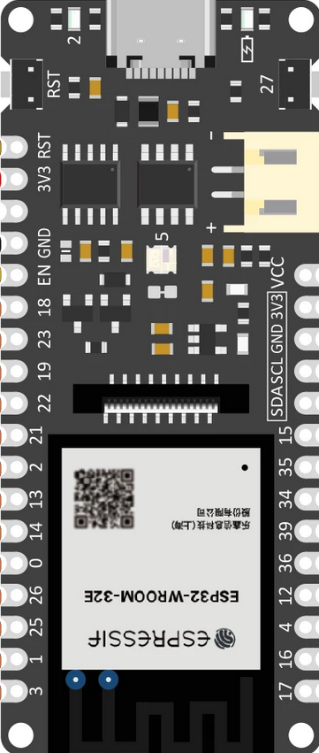
Pin Configuration and Descriptions

The FireBeetle 2 ESP32-E features a well-labeled pinout for easy prototyping. Below is the pin configuration:

Pin Name Functionality
3V3 3.3V power output
GND Ground
VIN Input voltage (3.3V - 5V)
D0-D13 Digital I/O pins (PWM-capable)
A0-A5 Analog input pins (12-bit ADC)
TX, RX UART communication pins
SCL, SDA I2C communication pins
MOSI, MISO, SCK SPI communication pins
EN Enable pin (used to reset the board)
RST Reset pin
DAC1, DAC2 Digital-to-Analog Converter pins

For a detailed pinout diagram, refer to the official DFRobot documentation:
Pinout Diagram

Usage Instructions

How to Use the FireBeetle 2 ESP32-E in a Circuit

  1. Powering the Board:

    • Use a USB-C cable to connect the board to your computer or a 5V power source.
    • Alternatively, supply 3.3V-5V to the VIN and GND pins.
  2. Programming the Board:

    • Install the Arduino IDE and add the ESP32 board package via the Board Manager.
    • Select "FireBeetle-ESP32" as the board type.
    • Connect the board to your computer and upload your code.
  3. Connecting Peripherals:

    • Use the GPIO pins to connect sensors, actuators, or other peripherals.
    • Ensure that the voltage levels of connected devices are compatible with the 3.3V logic of the board.
  4. Wireless Communication:

    • Use the built-in Wi-Fi and Bluetooth capabilities for wireless data transmission.
    • Libraries such as WiFi.h and BluetoothSerial.h can simplify development.

Important Considerations and Best Practices

  • Voltage Levels: Ensure all connected peripherals operate at 3.3V logic levels to avoid damaging the board.
  • Deep Sleep Mode: Use deep sleep mode to minimize power consumption in battery-powered applications.
  • Pin Multiplexing: Some pins have multiple functions (e.g., ADC, DAC, UART). Refer to the pinout diagram to avoid conflicts.
  • Firmware Updates: Keep the ESP32 firmware updated for optimal performance and security.

Example Code: Blinking an LED

The following example demonstrates how to blink an LED connected to pin D2:

// Define the pin for the LED
const int ledPin = 2; // D2 on the FireBeetle 2 ESP32-E

void setup() {
  pinMode(ledPin, OUTPUT); // Set the LED pin as an output
}

void loop() {
  digitalWrite(ledPin, HIGH); // Turn the LED on
  delay(1000);               // Wait for 1 second
  digitalWrite(ledPin, LOW);  // Turn the LED off
  delay(1000);               // Wait for 1 second
}

Example Code: Connecting to Wi-Fi

The following example demonstrates how to connect the FireBeetle 2 ESP32-E to a Wi-Fi network:

#include <WiFi.h>

// Replace with your network credentials
const char* ssid = "Your_SSID";
const char* password = "Your_PASSWORD";

void setup() {
  Serial.begin(115200); // Initialize serial communication
  WiFi.begin(ssid, password); // Start Wi-Fi connection

  // Wait for the connection to establish
  while (WiFi.status() != WL_CONNECTED) {
    delay(500);
    Serial.print(".");
  }
  Serial.println("\nWi-Fi connected!");
  Serial.print("IP Address: ");
  Serial.println(WiFi.localIP()); // Print the assigned IP address
}

void loop() {
  // Add your main code here
}

Troubleshooting and FAQs

Common Issues and Solutions

  1. The board is not detected by the computer:

    • Ensure the USB-C cable is functional and supports data transfer.
    • Install the required USB-to-serial driver for the FireBeetle 2 ESP32-E.
  2. Code upload fails:

    • Check that the correct board and COM port are selected in the Arduino IDE.
    • Press and hold the "BOOT" button on the board while uploading the code.
  3. Wi-Fi connection issues:

    • Verify the SSID and password are correct.
    • Ensure the Wi-Fi network is within range and operational.
  4. Peripherals not working as expected:

    • Double-check the wiring and pin assignments in your code.
    • Ensure the peripherals are compatible with 3.3V logic levels.

FAQs

Q: Can I power the board using a LiPo battery?
A: Yes, the FireBeetle 2 ESP32-E supports LiPo batteries via the JST connector. Ensure the battery voltage is within the supported range.

Q: Does the board support OTA (Over-The-Air) updates?
A: Yes, the ESP32-E chip supports OTA updates. Use libraries like ArduinoOTA to implement this feature.

Q: Can I use the board with MicroPython?
A: Yes, the FireBeetle 2 ESP32-E is compatible with MicroPython. Flash the MicroPython firmware to get started.

Q: What is the maximum current output of the 3.3V pin?
A: The 3.3V pin can supply up to 500mA, depending on the input power source.

This concludes the documentation for the FireBeetle 2 ESP32-E (N16R2) IoT Board. For further assistance, refer to the official DFRobot resources.