Cirkit Designer Logo
Cirkit Designer
Your all-in-one circuit design IDE
Home / 
Component Documentation

How to Use MAX4466: Examples, Pinouts, and Specs

Image of MAX4466
Cirkit Designer LogoDesign with MAX4466 in Cirkit Designer

Introduction

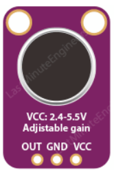
The MAX4466 is an adjustable-gain microphone amplifier module that is designed to amplify the analog signals from an electret microphone. It is equipped with a low-noise preamplifier, variable gain control, and an onboard microphone, making it ideal for a variety of audio applications such as voice recognition, audio recording, and sound detection.

Explore Projects Built with MAX4466

Use Cirkit Designer to design, explore, and prototype these projects online. Some projects support real-time simulation. Click "Open Project" to start designing instantly!
ESP8266 NodeMCU Controlled Multi-Channel Thermocouple Interface
Image of Temperature Data Acquisition_Task2: A project utilizing MAX4466 in a practical application
This circuit is designed to interface multiple MAX6675 thermocouple-to-digital converter modules with an ESP8266 NodeMCU microcontroller. Each MAX6675 module is connected to a temperature sensor and the ESP8266 is configured to communicate with the modules via SPI to read temperature data. The ESP8266 NodeMCU manages the chip select (CS) lines individually for each MAX6675 module, allowing for multiple temperature readings from different sensors.
Cirkit Designer LogoOpen Project in Cirkit Designer
Dual-Microcontroller Audio Processing System with Visual Indicators and Battery Management
Image of proto thesis 2: A project utilizing MAX4466 in a practical application
This is a portable audio-visual device featuring two Wemos microcontrollers for processing, Adafruit MAX4466 microphone amplifiers for audio input, and an LCD TFT screen for display. It includes power management with TP4056 modules and LiPo batteries, and user-controlled toggle and rocker switches.
Cirkit Designer LogoOpen Project in Cirkit Designer
ESP32-Based Smart Data Logger with LCD Display and Microphone
Image of IOT: A project utilizing MAX4466 in a practical application
This circuit features an ESP32 microcontroller interfaced with a MAX4466 microphone module, a Micro SD Card module, and a 16x2 I2C LCD display. The ESP32 reads audio data from the MAX4466, stores data on the SD card, and displays information on the LCD. A 7805 voltage regulator provides power to the components.
Cirkit Designer LogoOpen Project in Cirkit Designer
Arduino Mega 2560 Based Multi-Channel Thermocouple Reader
Image of thermostat-test: A project utilizing MAX4466 in a practical application
This circuit is designed to interface with multiple MAX6675 thermocouple-to-digital converter modules using an Arduino Mega 2560 as the central processing unit. The Arduino reads temperature data from the MAX6675 modules over a shared SPI bus, with individual chip select (CS) lines for each module to enable multiplexing. The circuit is likely used for monitoring multiple temperature points, possibly in an industrial setting where precise temperature control and monitoring are critical.
Cirkit Designer LogoOpen Project in Cirkit Designer

Explore Projects Built with MAX4466

Use Cirkit Designer to design, explore, and prototype these projects online. Some projects support real-time simulation. Click "Open Project" to start designing instantly!
Image of Temperature Data Acquisition_Task2: A project utilizing MAX4466 in a practical application
ESP8266 NodeMCU Controlled Multi-Channel Thermocouple Interface
This circuit is designed to interface multiple MAX6675 thermocouple-to-digital converter modules with an ESP8266 NodeMCU microcontroller. Each MAX6675 module is connected to a temperature sensor and the ESP8266 is configured to communicate with the modules via SPI to read temperature data. The ESP8266 NodeMCU manages the chip select (CS) lines individually for each MAX6675 module, allowing for multiple temperature readings from different sensors.
Cirkit Designer LogoOpen Project in Cirkit Designer
Image of proto thesis 2: A project utilizing MAX4466 in a practical application
Dual-Microcontroller Audio Processing System with Visual Indicators and Battery Management
This is a portable audio-visual device featuring two Wemos microcontrollers for processing, Adafruit MAX4466 microphone amplifiers for audio input, and an LCD TFT screen for display. It includes power management with TP4056 modules and LiPo batteries, and user-controlled toggle and rocker switches.
Cirkit Designer LogoOpen Project in Cirkit Designer
Image of IOT: A project utilizing MAX4466 in a practical application
ESP32-Based Smart Data Logger with LCD Display and Microphone
This circuit features an ESP32 microcontroller interfaced with a MAX4466 microphone module, a Micro SD Card module, and a 16x2 I2C LCD display. The ESP32 reads audio data from the MAX4466, stores data on the SD card, and displays information on the LCD. A 7805 voltage regulator provides power to the components.
Cirkit Designer LogoOpen Project in Cirkit Designer
Image of thermostat-test: A project utilizing MAX4466 in a practical application
Arduino Mega 2560 Based Multi-Channel Thermocouple Reader
This circuit is designed to interface with multiple MAX6675 thermocouple-to-digital converter modules using an Arduino Mega 2560 as the central processing unit. The Arduino reads temperature data from the MAX6675 modules over a shared SPI bus, with individual chip select (CS) lines for each module to enable multiplexing. The circuit is likely used for monitoring multiple temperature points, possibly in an industrial setting where precise temperature control and monitoring are critical.
Cirkit Designer LogoOpen Project in Cirkit Designer

Common Applications and Use Cases

  • Voice-activated systems
  • Audio recording devices
  • Sound level detection
  • Environmental noise measurement
  • DIY audio projects

Technical Specifications

Key Technical Details

  • Supply Voltage (Vcc): 2.4V to 5.5V
  • Output Voltage Gain: Adjustable from 25x to 125x
  • Input Referred Noise: 24nV/√Hz (typical at 1kHz)
  • Quiescent Current: 24µA (typical)
  • THD+N: 0.04% (typical at 1kHz)

Pin Configuration and Descriptions

Pin Number Name Description
1 Vcc Power supply (2.4V to 5.5V)
2 GND Ground connection
3 OUT Amplified audio signal output
4 Gain Gain control voltage input (0V to Vcc)

Usage Instructions

How to Use the Component in a Circuit

  1. Power Supply: Connect the Vcc pin to a power source between 2.4V and 5.5V, and the GND pin to the ground of your circuit.
  2. Microphone Connection: The onboard microphone is already connected to the input of the amplifier. If you wish to use an external microphone, ensure it is an electret type and connect it appropriately.
  3. Gain Adjustment: The gain of the amplifier can be adjusted by applying a voltage to the Gain pin. This can be done using a potentiometer or a voltage divider connected to your power supply.
  4. Output Signal: The OUT pin provides the amplified signal. Connect this to the analog input of a microcontroller or another audio processing circuit.

Important Considerations and Best Practices

  • Use a clean power supply to minimize noise.
  • Keep the audio signal paths as short as possible to reduce interference.
  • If using an external microphone, ensure it is compatible with the MAX4466.
  • To prevent oscillations, keep the gain control wiring away from the output signal path.

Example Connection with Arduino UNO

// Example code for reading the output of the MAX4466 with an Arduino UNO

const int micPin = A0; // Connect the OUT pin of the MAX4466 to analog pin A0

void setup() {
  Serial.begin(9600);
}

void loop() {
  int micValue = analogRead(micPin); // Read the amplified signal
  Serial.println(micValue); // Print the value to the Serial Monitor
  delay(10); // Short delay for stability
}

Troubleshooting and FAQs

Common Issues Users Might Face

  • Low Output Volume: Ensure the gain is properly adjusted. If using an external microphone, check the connections and compatibility.
  • High Noise Levels: Verify the power supply is clean and stable. Keep signal paths short and away from sources of interference.
  • No Output Signal: Check all connections, including power supply and ground. Ensure the microphone is functioning.

Solutions and Tips for Troubleshooting

  • If experiencing noise, add a decoupling capacitor (e.g., 0.1µF) between Vcc and GND close to the module.
  • Use shielded cables for the microphone and output if the module is placed in a noisy environment.
  • Adjust the gain control gradually to find the optimal setting for your application.

FAQs

Q: Can I use the MAX4466 with a digital microphone? A: No, the MAX4466 is designed for use with electret microphones, which provide an analog output signal.

Q: What is the maximum gain I can achieve with this module? A: The MAX4466 can provide a maximum gain of 125x.

Q: How do I change the gain setting? A: Apply a voltage between 0V and Vcc to the Gain pin to adjust the gain from 25x to 125x.

Q: Can I power the MAX4466 with a 3.3V supply? A: Yes, the MAX4466 can operate with a supply voltage as low as 2.4V, so a 3.3V supply is suitable.

For further assistance or more complex issues, please refer to the manufacturer's datasheet or contact technical support.