How to Use 4x4 Keypad: Examples, Pinouts, and Specs
Introduction
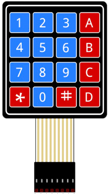
A 4x4 keypad is a matrix keypad consisting of 16 buttons arranged in 4 rows and 4 columns. It is used for inputting data in electronic devices, allowing users to enter numerical or alphanumeric data. This component is widely used in applications such as security systems, calculators, embedded systems, and other devices requiring user input.
The 4x4 keypad is compact, easy to interface with microcontrollers, and provides a simple way to capture user input. Its matrix design reduces the number of pins required for interfacing, making it an efficient choice for many projects.
Explore Projects Built with 4x4 Keypad

Explore Projects Built with 4x4 Keypad
Technical Specifications
- Number of Buttons: 16 (4 rows × 4 columns)
- Operating Voltage: 3.3V to 5V
- Current Consumption: Typically < 10mA
- Button Type: Momentary push buttons
- Interface Type: Matrix (row-column scanning)
- Dimensions: Varies by manufacturer, typically around 70mm × 70mm
- Connector Type: 8-pin header (4 row pins + 4 column pins)
Pin Configuration and Descriptions
The 4x4 keypad has 8 pins, corresponding to the 4 rows and 4 columns of the matrix. The pinout may vary slightly depending on the manufacturer, but the general configuration is as follows:
| Pin | Label | Description |
|---|---|---|
| 1 | R1 | Row 1 |
| 2 | R2 | Row 2 |
| 3 | R3 | Row 3 |
| 4 | R4 | Row 4 |
| 5 | C1 | Column 1 |
| 6 | C2 | Column 2 |
| 7 | C3 | Column 3 |
| 8 | C4 | Column 4 |
Usage Instructions
How to Use the 4x4 Keypad in a Circuit
Connect the Keypad to a Microcontroller:
- Connect the 4 row pins (R1–R4) and 4 column pins (C1–C4) to the GPIO pins of a microcontroller.
- Use pull-up or pull-down resistors if required by your microcontroller.
Scan the Keypad Matrix:
- To detect a button press, set one row pin HIGH at a time while keeping the others LOW.
- Read the column pins to determine which button in the active row is pressed.
- Repeat this process for all rows to scan the entire keypad.
Debounce the Buttons:
- Implement software or hardware debouncing to avoid false triggers caused by mechanical bouncing of the buttons.
Power Requirements:
- Ensure the keypad operates within its voltage range (3.3V–5V). Most microcontrollers can directly power the keypad.
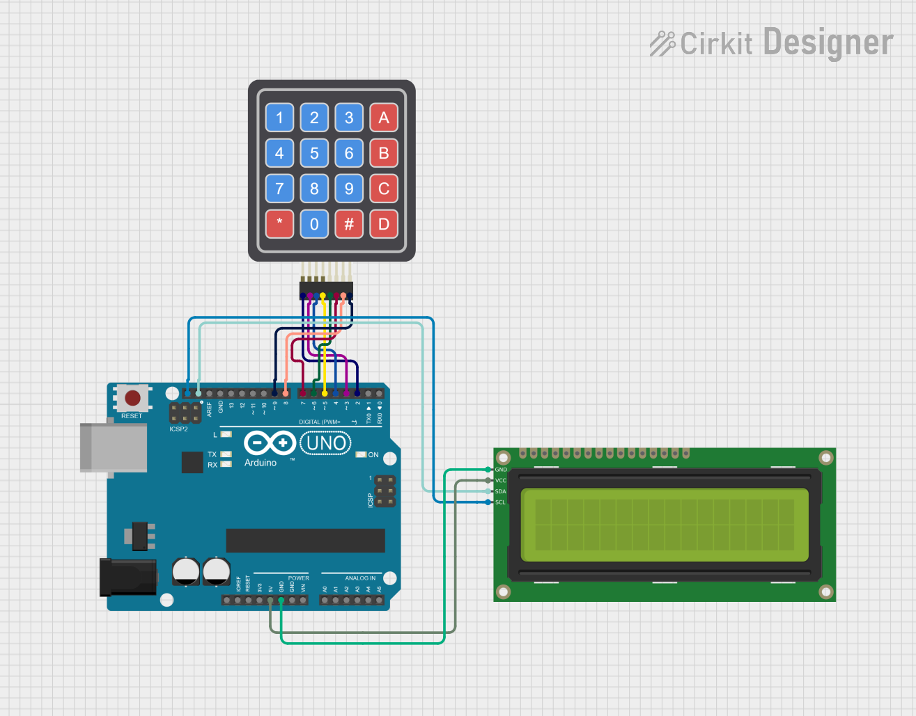
Example: Interfacing a 4x4 Keypad with Arduino UNO
Below is an example of how to interface a 4x4 keypad with an Arduino UNO using the Keypad library.
Circuit Connections
- Connect the keypad pins (R1–R4 and C1–C4) to Arduino digital pins 2–9.
- Use the following mapping:
- R1 → Pin 2
- R2 → Pin 3
- R3 → Pin 4
- R4 → Pin 5
- C1 → Pin 6
- C2 → Pin 7
- C3 → Pin 8
- C4 → Pin 9
Arduino Code
#include <Keypad.h>

// Define the rows and columns of the keypad
const byte ROWS = 4; // Number of rows
const byte COLS = 4; // Number of columns

// Define the keymap for the keypad
char keys[ROWS][COLS] = {
  {'1', '2', '3', 'A'},
  {'4', '5', '6', 'B'},
  {'7', '8', '9', 'C'},
  {'*', '0', '#', 'D'}
};

// Define the row and column pins connected to the Arduino
byte rowPins[ROWS] = {2, 3, 4, 5}; // Row pins
byte colPins[COLS] = {6, 7, 8, 9}; // Column pins

// Create a Keypad object
Keypad keypad = Keypad(makeKeymap(keys), rowPins, colPins, ROWS, COLS);

void setup() {
  Serial.begin(9600); // Initialize serial communication
  Serial.println("4x4 Keypad Test");
}

void loop() {
  char key = keypad.getKey(); // Get the key pressed

  if (key) {
    // If a key is pressed, print it to the Serial Monitor
    Serial.print("Key Pressed: ");
    Serial.println(key);
  }
}
Important Considerations and Best Practices
- Debouncing: Always implement debouncing to ensure reliable key detection.
- Pin Mapping: Double-check the pin mapping between the keypad and the microcontroller.
- Voltage Levels: Ensure the keypad's operating voltage matches the microcontroller's GPIO voltage levels.
- Library Usage: Use libraries like
Keypad.hfor easier implementation and reduced code complexity.
Troubleshooting and FAQs
Common Issues and Solutions
No Key Press Detected:
- Verify the wiring between the keypad and the microcontroller.
- Check if the row and column pins are correctly defined in the code.
Multiple Keys Detected at Once:
- Ensure proper debouncing is implemented in the code.
- Check for short circuits between the keypad pins.
Incorrect Key Presses:
- Verify the keymap in the code matches the physical layout of the keypad.
- Ensure the keypad is not damaged or worn out.
Keypad Not Responding:
- Confirm the keypad is powered within its operating voltage range.
- Test the keypad with a multimeter to ensure all buttons are functional.
FAQs
Q: Can I use the 4x4 keypad with a 3.3V microcontroller?
A: Yes, the 4x4 keypad can operate at 3.3V. Ensure the microcontroller's GPIO pins are compatible with the keypad's voltage levels.
Q: How do I extend the keypad's cable length?
A: Use shielded cables to reduce noise and interference. Keep the cable length as short as possible to maintain signal integrity.
Q: Can I use the keypad for alphanumeric input?
A: Yes, you can define a custom keymap in the code to assign alphanumeric characters to the keys.
Q: Is the keypad waterproof?
A: Most 4x4 keypads are not waterproof. If needed, use a waterproof keypad or enclose it in a protective casing.