How to Use NFC Tag Click: Examples, Pinouts, and Specs
Introduction
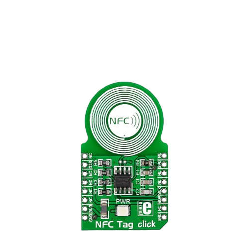
The NFC Tag Click (Manufacturer Part ID: MIKROE-1726) is a compact module designed for Near Field Communication (NFC) applications. It enables wireless data transfer between devices over short distances, typically up to a few centimeters. This module integrates an NFC chip and an antenna, making it ideal for a variety of NFC functionalities such as reading NFC tags, peer-to-peer communication, and contactless payments.
Explore Projects Built with NFC Tag Click
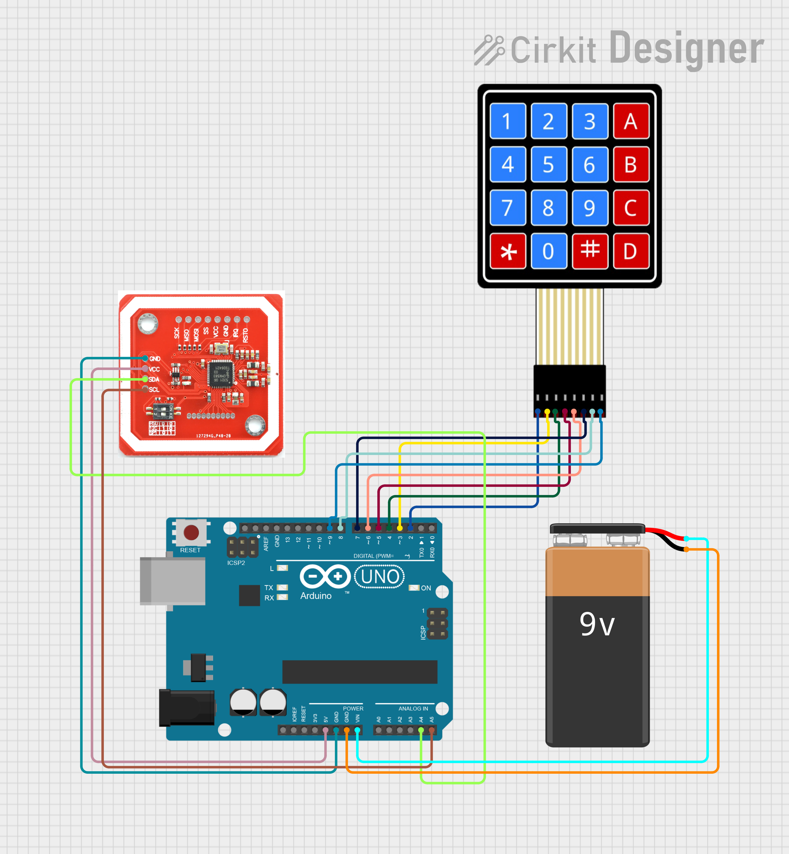

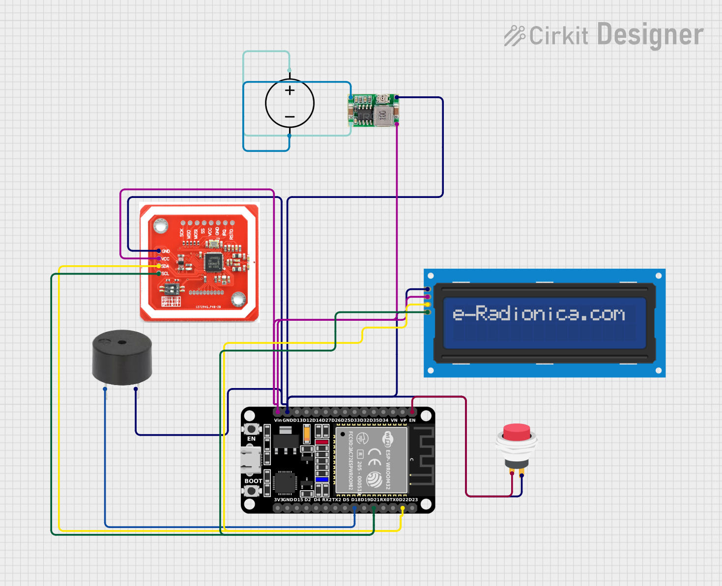

Explore Projects Built with NFC Tag Click
Common Applications
- Access Control Systems: Used in keyless entry systems for secure access.
- Contactless Payments: Facilitates secure and fast payment transactions.
- Data Exchange: Enables peer-to-peer communication between NFC-enabled devices.
- Smart Posters: Reads NFC tags embedded in posters for marketing or informational purposes.
- IoT Devices: Acts as a communication interface for Internet of Things (IoT) applications.
Technical Specifications
The following table outlines the key technical details of the NFC Tag Click module:
| Parameter | Specification |
|---|---|
| Manufacturer | MIKROE |
| Part ID | MIKROE-1726 |
| Communication Protocol | I2C or SPI |
| Operating Voltage | 3.3V |
| Interface Voltage | 3.3V (logic level) |
| NFC Chip | NXP NT3H1101/NT3H1201 |
| Frequency Range | 13.56 MHz |
| Antenna | Integrated PCB antenna |
| Operating Temperature | -40°C to +85°C |
| Dimensions | 28.6mm x 25.4mm |
Pin Configuration
The NFC Tag Click module uses a standard mikroBUS™ socket. The pinout is as follows:
| Pin | Name | Type | Description |
|---|---|---|---|
| 1 | AN | Analog Input | Not used in this module |
| 2 | RST | Digital Input | Reset pin for the NFC chip |
| 3 | CS | Digital Input | Chip Select for SPI communication |
| 4 | SCK | Digital Input | SPI Clock |
| 5 | MISO | Digital Output | SPI Master-In-Slave-Out |
| 6 | MOSI | Digital Input | SPI Master-Out-Slave-In |
| 7 | PWM | Digital Input | Not used in this module |
| 8 | INT | Digital Output | Interrupt pin for NFC events |
| 9 | TX | Digital Output | Not used in this module |
| 10 | RX | Digital Input | Not used in this module |
| 11 | SCL | Digital Input | I2C Clock |
| 12 | SDA | Digital Input | I2C Data |
| 13 | 3.3V | Power | 3.3V power supply |
| 14 | GND | Power | Ground |
Usage Instructions
How to Use the NFC Tag Click in a Circuit
- Power Supply: Connect the 3.3V and GND pins to a 3.3V power source.
- Communication Interface: Choose between I2C or SPI communication:
- For I2C, connect the SCL and SDA pins to the corresponding I2C pins on your microcontroller.
- For SPI, connect the CS, SCK, MISO, and MOSI pins to the corresponding SPI pins on your microcontroller.
- Reset and Interrupt: Optionally, connect the RST pin to a GPIO pin for resetting the NFC chip and the INT pin to monitor NFC events.
- Antenna Placement: Ensure the integrated antenna is not obstructed by metal objects to maintain optimal NFC performance.
Important Considerations
- Voltage Levels: The module operates at 3.3V logic levels. Use a level shifter if your microcontroller operates at 5V.
- Antenna Clearance: Avoid placing the module near metal surfaces or enclosures that could interfere with the NFC signal.
- Communication Mode: Configure your microcontroller to use either I2C or SPI, but not both simultaneously.
Example Code for Arduino UNO
Below is an example of how to use the NFC Tag Click with an Arduino UNO via I2C:
#include <Wire.h> // Include the I2C library

#define NFC_I2C_ADDRESS 0x55 // Default I2C address for the NFC chip

void setup() {
  Wire.begin(); // Initialize I2C communication
  Serial.begin(9600); // Initialize serial communication for debugging

  // Send a reset command to the NFC chip
  Wire.beginTransmission(NFC_I2C_ADDRESS);
  Wire.write(0x00); // Example command to reset the NFC chip
  Wire.endTransmission();

  Serial.println("NFC Tag Click initialized.");
}

void loop() {
  // Example: Read data from the NFC chip
  Wire.requestFrom(NFC_I2C_ADDRESS, 16); // Request 16 bytes of data
  while (Wire.available()) {
    char c = Wire.read(); // Read a byte
    Serial.print(c); // Print the byte to the serial monitor
  }
  Serial.println();

  delay(1000); // Wait for 1 second before the next read
}
Notes:
- Replace the I2C address (
0x55) and commands with the appropriate values based on your NFC chip's datasheet. - Ensure the Arduino UNO is configured to operate at 3.3V logic levels or use a level shifter.
Troubleshooting and FAQs
Common Issues
No Response from the NFC Module
- Cause: Incorrect wiring or communication protocol mismatch.
- Solution: Double-check the connections and ensure the correct protocol (I2C or SPI) is selected.
NFC Tag Not Detected
- Cause: Antenna interference or improper placement of the NFC tag.
- Solution: Ensure the NFC tag is within the module's range and there are no metal objects nearby.
Data Corruption
- Cause: Noise or incorrect voltage levels.
- Solution: Use proper decoupling capacitors and ensure the module operates at 3.3V.
FAQs
Can the NFC Tag Click work with 5V microcontrollers?
- Yes, but you must use a level shifter to convert the 5V logic levels to 3.3V.
What is the maximum range of the NFC Tag Click?
- The typical range is up to 5 cm, depending on the NFC tag and environmental conditions.
Can I use both I2C and SPI simultaneously?
- No, you must choose one communication protocol at a time.
Is the antenna replaceable?
- No, the module comes with an integrated PCB antenna that cannot be replaced.
By following this documentation, you can effectively integrate the NFC Tag Click into your projects and troubleshoot common issues.