
How to Use START PUSH BUTTON: Examples, Pinouts, and Specs
 Design with START PUSH BUTTON in Cirkit Designer
Introduction
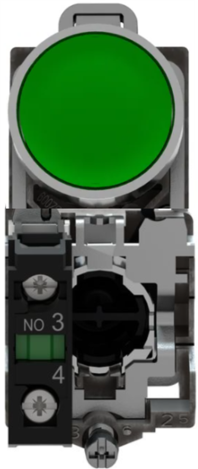
The START PUSH BUTTON (Manufacturer: Schneider, Part ID: XB4-BA31) is a momentary switch designed to complete an electrical circuit when pressed. It is commonly used to initiate a function or process in electronic devices, industrial control systems, and automation applications. This robust and reliable component is ideal for environments requiring frequent operation and high durability.
Explore Projects Built with START PUSH BUTTON
 Open Project in Cirkit Designer
 Open Project in Cirkit Designer
 Open Project in Cirkit Designer
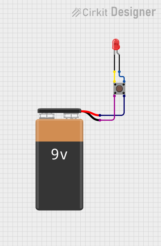 Open Project in Cirkit Designer
Explore Projects Built with START PUSH BUTTON
Open Project in Cirkit DesignerOpen Project in Cirkit DesignerOpen Project in Cirkit DesignerOpen Project in Cirkit DesignerCommon Applications
- Industrial machinery start/stop controls
- Automation systems
- Consumer electronics
- Robotics and mechatronics
- Emergency or manual override systems
Technical Specifications
Key Technical Details
| Parameter | Specification |
|---|---|
| Manufacturer | Schneider |
| Part ID | XB4-BA31 |
| Switch Type | Momentary push button |
| Contact Configuration | Normally Open (NO) |
| Operating Voltage | 24V DC / 240V AC (max) |
| Operating Current | 10A (max) |
| Mechanical Durability | 1,000,000 cycles |
| Mounting Style | Panel mount |
| Button Material | Plastic (high durability) |
| Operating Temperature | -25°C to +70°C |
| IP Rating | IP66 (dust-tight and water-resistant) |
Pin Configuration and Descriptions
The START PUSH BUTTON has two terminals for electrical connections. These terminals are used to integrate the button into a circuit.
| Pin Number | Label | Description |
|---|---|---|
| 1 | NO | Normally Open terminal |
| 2 | COM | Common terminal |
Note: When the button is pressed, the NO terminal connects to the COM terminal, completing the circuit.
Usage Instructions
How to Use the Component in a Circuit
Wiring the Button:
- Connect the COM terminal to the ground or common point in your circuit.
- Connect the NO terminal to the input of the device or circuit you wish to control.
- Ensure proper insulation and secure connections to avoid short circuits.
Power Supply:
- Verify that the operating voltage and current of the circuit are within the button's rated specifications (24V DC / 240V AC, 10A max).
Mounting:
- Install the button in a panel or enclosure using the provided mounting hardware.
- Ensure the button is securely fastened and aligned for easy operation.
Testing:
- After wiring, press the button to verify that it completes the circuit and initiates the desired function.
Important Considerations and Best Practices
- Debouncing: When used in digital circuits, the button may produce noise or multiple signals due to mechanical bouncing. Use a debouncing circuit or software logic to ensure reliable operation.
- Current Limiting: If the button is used to control high-current devices, include a relay or transistor to handle the load.
- Environmental Protection: Ensure the button's IP66 rating is maintained by properly sealing the panel or enclosure.
Example: Connecting to an Arduino UNO
The START PUSH BUTTON can be easily interfaced with an Arduino UNO for digital input. Below is an example circuit and code:
Circuit Diagram
- Connect the COM terminal to the Arduino's GND pin.
- Connect the NO terminal to a digital input pin (e.g., pin 2) on the Arduino.
- Use a pull-down resistor (10kΩ) between the NO terminal and GND to ensure a stable LOW state when the button is not pressed.
Arduino Code
// Define the pin connected to the push button
const int buttonPin = 2;  // Digital pin 2 for button input
const int ledPin = 13;    // Built-in LED pin for output

void setup() {
  pinMode(buttonPin, INPUT);  // Set button pin as input
  pinMode(ledPin, OUTPUT);   // Set LED pin as output
  digitalWrite(ledPin, LOW); // Ensure LED is off initially
}

void loop() {
  int buttonState = digitalRead(buttonPin); // Read button state

  if (buttonState == HIGH) {
    // If button is pressed, turn on the LED
    digitalWrite(ledPin, HIGH);
  } else {
    // If button is not pressed, turn off the LED
    digitalWrite(ledPin, LOW);
  }
}
Note: The pull-down resistor ensures the button pin reads LOW when the button is not pressed, preventing false triggers.
Troubleshooting and FAQs
Common Issues and Solutions
Button Not Responding:
- Cause: Loose or incorrect wiring.
- Solution: Verify all connections and ensure the terminals are securely fastened.
Button Stuck or Hard to Press:
- Cause: Mechanical wear or debris.
- Solution: Clean the button and check for obstructions. Replace if necessary.
Multiple Signals Detected:
- Cause: Mechanical bouncing.
- Solution: Use a debouncing circuit or software logic to filter out noise.
Circuit Overload:
- Cause: Exceeding the button's current rating.
- Solution: Use a relay or transistor to handle high-current loads.
FAQs
Q: Can this button be used outdoors?
A: Yes, the button has an IP66 rating, making it suitable for outdoor use in dust-tight and water-resistant environments.
Q: Is the button compatible with 5V logic circuits?
A: Yes, the button can be used with 5V logic circuits, but ensure proper pull-up or pull-down resistors are used for stable operation.
Q: Can I use this button to control AC devices?
A: Yes, the button supports up to 240V AC. However, for high-power devices, use a relay or contactor to handle the load safely.
Q: How do I replace the button if it wears out?
A: The button is panel-mounted and can be easily replaced by unscrewing it from the panel and disconnecting the terminals.
This documentation provides all the necessary details to effectively use and troubleshoot the Schneider XB4-BA31 START PUSH BUTTON in various applications.