How to Use Loadcell Indicator: Examples, Pinouts, and Specs
Introduction
The Weilo M60 Loadcell Indicator is a precision device designed to display the weight or force measured by a load cell. It converts the electrical signals generated by the load cell into a readable format, typically shown on a digital display. The M60 is equipped with advanced features such as calibration options, data logging, and compatibility with various load cell types, making it a versatile tool for industrial, commercial, and laboratory applications.
Explore Projects Built with Loadcell Indicator

Explore Projects Built with Loadcell Indicator
Common Applications and Use Cases
- Industrial Weighing Systems: Used in conveyor belts, hoppers, and tank weighing systems.
- Material Testing: Measures force or weight in tensile and compression testing machines.
- Retail and Commercial Scales: Provides accurate weight readings for goods.
- Automation Systems: Integrates with PLCs and other control systems for automated processes.
- Research and Development: Used in labs for precise force measurement and data analysis.
Technical Specifications
Key Technical Details
| Parameter | Specification |
|---|---|
| Manufacturer | Weilo |
| Part ID | M60 |
| Input Signal Range | 0.5 mV/V to 4.0 mV/V |
| Excitation Voltage | 5V DC |
| Display Type | 6-digit LED display |
| Display Resolution | Up to 1/10,000 |
| Power Supply | 24V DC ±10% |
| Operating Temperature | -10°C to 50°C |
| Communication Interfaces | RS232, RS485, Modbus RTU |
| Calibration Options | Manual and automatic |
| Mounting Style | Panel-mounted |
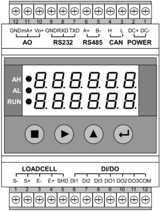
Pin Configuration and Descriptions
The M60 Loadcell Indicator features a terminal block for wiring connections. Below is the pin configuration:
Load Cell Input Terminals
| Pin Number | Label | Description |
|---|---|---|
| 1 | +EXC | Positive excitation voltage to load cell |
| 2 | -EXC | Negative excitation voltage to load cell |
| 3 | +SIG | Positive signal from load cell |
| 4 | -SIG | Negative signal from load cell |
Power and Communication Terminals
| Pin Number | Label | Description |
|---|---|---|
| 5 | +24V | Positive power supply (24V DC) |
| 6 | GND | Ground connection |
| 7 | TX | Transmit data (RS232/RS485) |
| 8 | RX | Receive data (RS232/RS485) |
Usage Instructions
How to Use the Component in a Circuit
- Wiring the Load Cell:
- Connect the load cell's excitation wires to the
+EXCand-EXCterminals. - Connect the load cell's signal wires to the
+SIGand-SIGterminals.
- Connect the load cell's excitation wires to the
- Powering the Indicator:
- Supply 24V DC to the
+24VandGNDterminals.
- Supply 24V DC to the
- Calibrating the Indicator:
- Enter calibration mode using the front panel buttons.
- Follow the on-screen instructions to set the zero point and span using known weights.
- Data Communication:
- Connect the RS232 or RS485 terminals to a computer or PLC for data logging or remote monitoring.
- Use the Modbus RTU protocol for communication.
Important Considerations and Best Practices
- Ensure the load cell is properly mounted and free from mechanical interference.
- Use shielded cables for the load cell connections to minimize electrical noise.
- Avoid overloading the load cell beyond its rated capacity to prevent damage.
- Regularly calibrate the indicator to maintain accuracy.
- If using RS485 communication, ensure proper termination resistors are installed.
Arduino UNO Example Code
The M60 Loadcell Indicator can communicate with an Arduino UNO via RS232. Below is an example code snippet for reading data:
#include <SoftwareSerial.h>

// Define RX and TX pins for RS232 communication
SoftwareSerial loadcellSerial(10, 11); // RX = pin 10, TX = pin 11

void setup() {
  Serial.begin(9600); // Initialize Serial Monitor
  loadcellSerial.begin(9600); // Initialize RS232 communication

  Serial.println("Weilo M60 Loadcell Indicator - Arduino Example");
}

void loop() {
  // Check if data is available from the loadcell indicator
  if (loadcellSerial.available()) {
    String weightData = ""; // Variable to store weight data

    // Read data from the loadcell indicator
    while (loadcellSerial.available()) {
      char c = loadcellSerial.read();
      weightData += c; // Append each character to the string
    }

    // Print the received weight data to the Serial Monitor
    Serial.println("Weight: " + weightData);
  }

  delay(500); // Wait for 500ms before the next read
}
Troubleshooting and FAQs
Common Issues and Solutions
No Display or Power:
- Cause: Incorrect power supply connection.
- Solution: Verify the
+24VandGNDconnections and ensure the power supply is within the specified range.
Inaccurate Weight Readings:
- Cause: Load cell not calibrated or improperly mounted.
- Solution: Recalibrate the indicator and check the load cell's mechanical setup.
Communication Failure:
- Cause: Incorrect wiring or baud rate mismatch.
- Solution: Verify the RS232/RS485 connections and ensure the baud rate matches the indicator's settings.
Fluctuating Readings:
- Cause: Electrical noise or unstable load cell.
- Solution: Use shielded cables and ensure the load cell is securely mounted.
FAQs
Q1: Can the M60 handle multiple load cells?
A1: No, the M60 is designed to work with a single load cell. For multiple load cells, use a summing box.
Q2: How often should I calibrate the indicator?
A2: Calibration frequency depends on usage, but it is recommended to calibrate at least once every six months.
Q3: Is the M60 compatible with all load cells?
A3: The M60 is compatible with most strain gauge-based load cells with an output range of 0.5 mV/V to 4.0 mV/V.
Q4: Can I use the M60 in outdoor environments?
A4: The M60 is not weatherproof. Use it in a controlled environment or within an enclosure for outdoor applications.
This concludes the documentation for the Weilo M60 Loadcell Indicator. For further assistance, refer to the manufacturer's user manual or contact technical support.