
How to Use YF-S201: Examples, Pinouts, and Specs
 Design with YF-S201 in Cirkit Designer
Introduction
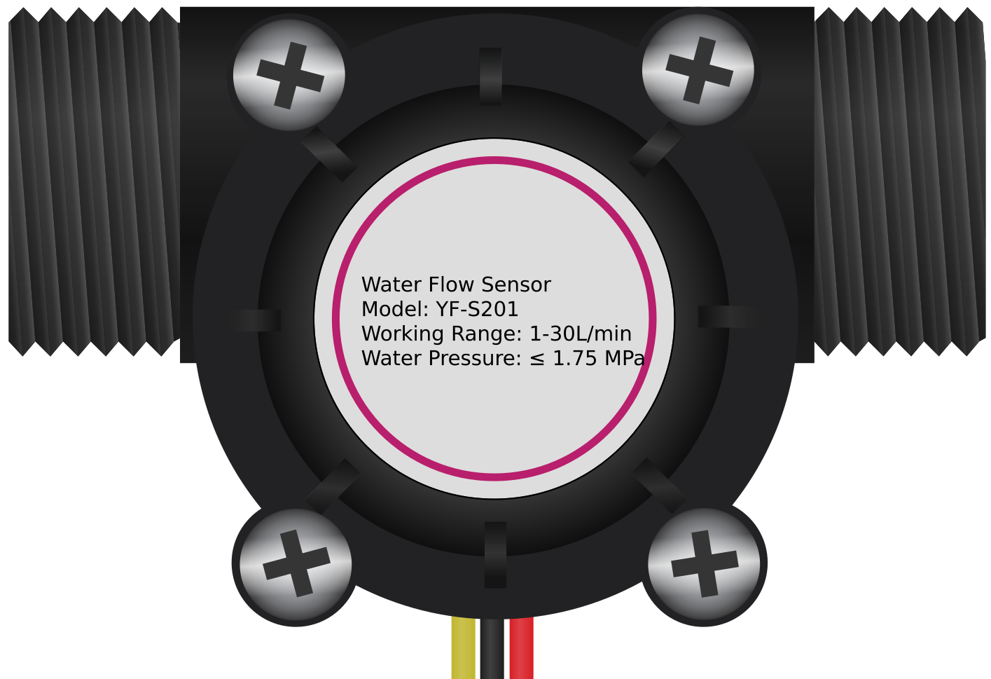
The YF-S201 is a water flow sensor designed to measure the flow rate of water in a pipe. It operates using a Hall effect sensor that detects the movement of a rotor inside the sensor. As water flows through the sensor, the rotor spins, and the Hall effect sensor generates a pulse signal proportional to the flow rate. This makes the YF-S201 an ideal choice for applications requiring accurate water flow monitoring, such as:
- Water dispensers
- Irrigation systems
- Industrial water flow monitoring
- Smart home water management systems
- Liquid flow measurement in research and development
Explore Projects Built with YF-S201
 Open Project in Cirkit Designer
 Open Project in Cirkit Designer
 Open Project in Cirkit Designer
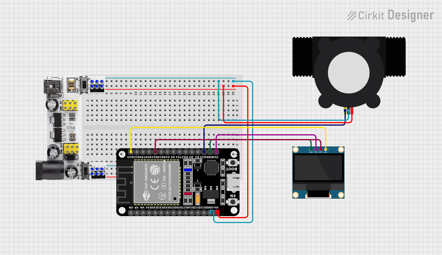 Open Project in Cirkit Designer
Explore Projects Built with YF-S201
Open Project in Cirkit DesignerOpen Project in Cirkit DesignerOpen Project in Cirkit DesignerOpen Project in Cirkit DesignerTechnical Specifications
The YF-S201 water flow sensor has the following key technical details:
| Parameter | Value |
|---|---|
| Operating Voltage | 5V to 18V DC |
| Operating Current | ≤ 15 mA (at 5V DC) |
| Flow Rate Range | 1 to 30 liters per minute (L/min) |
| Output Pulse Frequency | F = 7.5 * Q (Q = flow rate in L/min) |
| Maximum Water Pressure | 1.75 MPa |
| Operating Temperature | -25°C to 80°C |
| Sensor Body Material | Nylon |
| Output Signal | Pulse signal (digital) |
Pin Configuration and Descriptions
The YF-S201 has three wires for connection:
| Wire Color | Function | Description |
|---|---|---|
| Red | VCC | Connect to the positive supply voltage (5V to 18V) |
| Black | GND | Connect to ground |
| Yellow | Signal (Pulse Out) | Outputs the pulse signal proportional to flow rate |
Usage Instructions
How to Use the YF-S201 in a Circuit
- Power the Sensor: Connect the red wire to a 5V to 18V DC power source and the black wire to ground.
- Read the Signal: Connect the yellow wire to a microcontroller's digital input pin to read the pulse signal.
- Calculate Flow Rate: Use the formula
Flow Rate (L/min) = Pulse Frequency / 7.5to calculate the flow rate based on the pulse frequency.
Important Considerations and Best Practices
- Ensure the water flow direction matches the arrow printed on the sensor body.
- Avoid exposing the sensor to water pressures exceeding 1.75 MPa to prevent damage.
- Use a pull-up resistor (typically 10kΩ) on the signal line if the microcontroller requires it for stable readings.
- Filter the water before it enters the sensor to prevent debris from clogging the rotor.
- Mount the sensor horizontally for optimal performance and accuracy.
Example Code for Arduino UNO
The following code demonstrates how to interface the YF-S201 with an Arduino UNO to measure and display the water flow rate:
// YF-S201 Water Flow Sensor Example Code
// Connect the sensor's red wire to 5V, black wire to GND, and yellow wire to pin 2.

volatile int pulseCount = 0; // Variable to store the pulse count
float flowRate = 0.0;        // Variable to store the flow rate in L/min
unsigned long lastTime = 0;  // Variable to store the last time measurement was taken

void setup() {
  pinMode(2, INPUT_PULLUP); // Set pin 2 as input with pull-up resistor
  attachInterrupt(digitalPinToInterrupt(2), countPulse, RISING);
  // Attach interrupt to pin 2, triggered on rising edge
  Serial.begin(9600); // Initialize serial communication at 9600 baud
}

void loop() {
  unsigned long currentTime = millis(); // Get the current time in milliseconds
  if (currentTime - lastTime >= 1000) {
    // Calculate flow rate every second
    flowRate = (pulseCount / 7.5); // Convert pulse count to flow rate in L/min
    Serial.print("Flow Rate: ");
    Serial.print(flowRate);
    Serial.println(" L/min");
    pulseCount = 0; // Reset pulse count for the next measurement
    lastTime = currentTime; // Update the last time measurement was taken
  }
}

void countPulse() {
  pulseCount++; // Increment pulse count on each pulse
}
Notes on the Code
- The
countPulsefunction is triggered by an interrupt on pin 2 whenever a pulse is detected. - The flow rate is calculated every second and displayed via the serial monitor.
- Ensure the Arduino UNO is powered appropriately and connected to the sensor as described.
Troubleshooting and FAQs
Common Issues and Solutions
No Pulse Signal Detected
- Verify the wiring connections, especially the yellow signal wire.
- Ensure the water is flowing through the sensor and the rotor is spinning.
- Check if the microcontroller's input pin is configured correctly.
Inaccurate Flow Rate Readings
- Ensure the sensor is mounted horizontally and the water flow direction matches the arrow.
- Check for debris or blockages in the sensor that may hinder rotor movement.
- Verify the formula used to calculate the flow rate is correct.
Sensor Not Responding
- Confirm the power supply voltage is within the specified range (5V to 18V).
- Inspect the sensor for physical damage or leaks.
FAQs
Q: Can the YF-S201 measure liquids other than water?
A: The YF-S201 is designed for water. Using it with other liquids may affect accuracy or damage the sensor.
Q: How do I protect the sensor from debris?
A: Install a water filter upstream of the sensor to prevent debris from entering and clogging the rotor.
Q: What is the maximum cable length for the signal wire?
A: For best performance, keep the signal wire as short as possible (less than 1 meter). Use shielded cables for longer distances to reduce noise.
Q: Can I use the YF-S201 with a 3.3V microcontroller?
A: Yes, but you may need a level shifter or voltage divider to ensure the signal voltage is compatible with the microcontroller's input.
By following this documentation, you can effectively integrate the YF-S201 water flow sensor into your projects for accurate and reliable water flow measurement.