How to Use 433 MHz RF Receiver: Examples, Pinouts, and Specs
Introduction
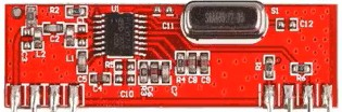
The 433 MHz RF Receiver is a wireless communication module designed to receive radio frequency signals at 433 MHz. It is widely used in applications requiring low-power, short-range communication. This component is commonly paired with a 433 MHz RF Transmitter to create a complete wireless communication system.
Explore Projects Built with 433 MHz RF Receiver


Explore Projects Built with 433 MHz RF Receiver
Common Applications and Use Cases
- Remote controls for home automation systems
- Wireless alarm and security systems
- Sensor networks for IoT (Internet of Things) devices
- Data transmission in hobbyist projects, such as Arduino-based systems
- Wireless weather stations
Technical Specifications
The 433 MHz RF Receiver is a compact and efficient module with the following key specifications:
| Parameter | Value |
|---|---|
| Operating Frequency | 433 MHz |
| Operating Voltage | 3.3V to 5V |
| Operating Current | 4 mA to 5.5 mA |
| Sensitivity | -105 dBm (typical) |
| Data Rate | Up to 10 kbps |
| Communication Range | Up to 50-100 meters (line of sight) |
| Modulation Type | Amplitude Shift Keying (ASK) |
Pin Configuration and Descriptions
The 433 MHz RF Receiver typically has 4 pins, as described in the table below:
| Pin | Name | Description |
|---|---|---|
| 1 | VCC | Power supply pin. Connect to 3.3V or 5V depending on your system requirements. |
| 2 | GND | Ground pin. Connect to the ground of your circuit. |
| 3 | DATA | Data output pin. Outputs the received signal for further processing. |
| 4 | ANT | Antenna pin. Connect to an external antenna for better signal reception. |
Usage Instructions
How to Use the 433 MHz RF Receiver in a Circuit
- Power the Module: Connect the VCC pin to a 3.3V or 5V power source and the GND pin to the ground of your circuit.
- Connect the Data Pin: Attach the DATA pin to the input pin of a microcontroller (e.g., Arduino) or a decoder IC for signal processing.
- Attach an Antenna: For optimal performance, connect a 17 cm wire to the ANT pin to act as an antenna.
- Pair with a Transmitter: Ensure the 433 MHz RF Transmitter is configured to send data to the receiver.
Important Considerations and Best Practices
- Antenna Placement: Use a straight wire of approximately 17 cm as an antenna for maximum range and signal quality.
- Power Supply: Ensure a stable power supply to avoid noise and interference in the received signal.
- Interference: Avoid placing the module near high-frequency devices or metal objects that may cause interference.
- Data Decoding: Use a microcontroller or decoder IC to process the received data. Libraries like
VirtualWireorRadioHeadcan simplify this process when using an Arduino.
Example: Connecting to an Arduino UNO
Below is an example of how to use the 433 MHz RF Receiver with an Arduino UNO to receive data:
Circuit Connections
- Connect the VCC pin of the receiver to the 5V pin on the Arduino.
- Connect the GND pin of the receiver to the GND pin on the Arduino.
- Connect the DATA pin of the receiver to digital pin 11 on the Arduino.
- Attach a 17 cm wire to the ANT pin for the antenna.
Arduino Code Example
#include <VirtualWire.h> // Include the VirtualWire library

void setup() {
  Serial.begin(9600); // Initialize serial communication at 9600 baud
  vw_setup(2000);     // Set the data rate to 2000 bits per second
  vw_set_rx_pin(11);  // Set the receiver data pin to digital pin 11
  vw_rx_start();      // Start the receiver
}

void loop() {
  uint8_t buffer[VW_MAX_MESSAGE_LEN]; // Buffer to store received messages
  uint8_t bufferLength = VW_MAX_MESSAGE_LEN; // Length of the buffer

  if (vw_get_message(buffer, &bufferLength)) { // Check if a message is received
    Serial.print("Received: ");
    for (int i = 0; i < bufferLength; i++) {
      Serial.print((char)buffer[i]); // Print each character of the message
    }
    Serial.println(); // Print a new line after the message
  }
}
Notes on the Code
- The
VirtualWirelibrary is used to simplify communication with the RF module. - Ensure the transmitter is configured to send data at the same data rate (2000 bps in this example).
Troubleshooting and FAQs
Common Issues and Solutions
No Signal Received
- Ensure the transmitter and receiver are operating at the same frequency (433 MHz).
- Check the antenna connection and placement for both modules.
- Verify that the power supply is stable and within the specified range.
Interference or Noise in the Signal
- Use a decoupling capacitor (e.g., 0.1 µF) across the power supply pins to reduce noise.
- Avoid placing the module near other RF devices or metal objects.
Short Communication Range
- Ensure the antenna is the correct length (17 cm for 433 MHz).
- Check for obstacles or interference in the line of sight.
Data Not Decoded Properly
- Verify that the data rate and protocol match between the transmitter and receiver.
- Use a library like
VirtualWireorRadioHeadto simplify data decoding.
FAQs
Q: Can I use the 433 MHz RF Receiver with a 3.3V system?
A: Yes, the module supports an operating voltage range of 3.3V to 5V. Ensure the transmitter is also compatible with the same voltage.
Q: What is the maximum range of the 433 MHz RF Receiver?
A: The range is typically 50-100 meters in an open, line-of-sight environment. Obstacles and interference may reduce the range.
Q: Do I need an external antenna?
A: Yes, connecting a 17 cm wire to the ANT pin significantly improves signal reception and range.
Q: Can I use multiple receivers with one transmitter?
A: Yes, a single transmitter can send data to multiple receivers as long as they are within range and configured to the same frequency and data rate.