How to Use ANTI THEFT ALARM: Examples, Pinouts, and Specs
Anti-Theft Alarm Documentation
Manufacturer: 999
Part ID: FF
Introduction
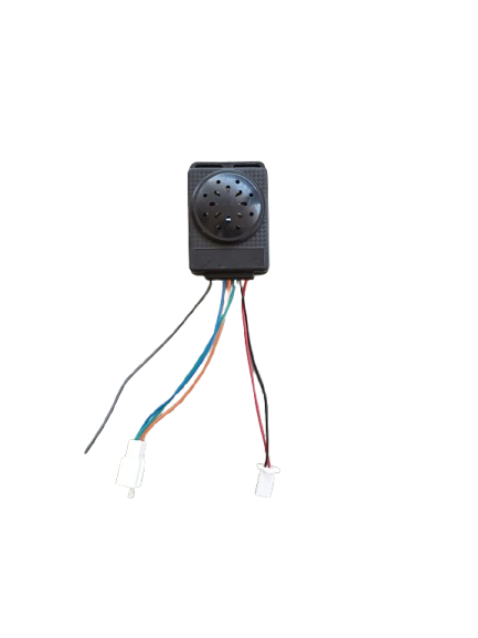
The Anti-Theft Alarm (Part ID: FF) is a security device designed to detect unauthorized entry or theft. When triggered, it emits a loud sound or sends an alert to a monitoring system, effectively deterring intruders and notifying users of potential security breaches. This component is versatile and can be integrated into various security systems, including home security setups, vehicle alarms, and industrial monitoring systems.
Common Applications
- Home Security Systems: Detects unauthorized entry into homes or buildings.
- Vehicle Security: Alerts users of potential theft or tampering with vehicles.
- Industrial Monitoring: Protects valuable equipment or restricted areas.
- Personal Safety Devices: Used in portable alarms for personal security.
Technical Specifications
The following table outlines the key technical details of the Anti-Theft Alarm:
| Parameter | Value | Description |
|---|---|---|
| Operating Voltage | 5V - 12V DC | Voltage range required for operation. |
| Current Consumption | 100mA (typical) | Average current drawn during operation. |
| Sound Output Level | 90-110 dB | Loudness of the alarm sound. |
| Trigger Mechanism | Digital Input (High/Low Signal) | Activates when a HIGH signal is received. |
| Dimensions | 50mm x 30mm x 20mm | Compact size for easy integration. |
| Operating Temperature | -10°C to 50°C | Suitable for indoor and outdoor environments. |
Pin Configuration
| Pin Name | Pin Number | Description |
|---|---|---|
| VCC | 1 | Connect to the positive supply voltage (5V-12V). |
| GND | 2 | Connect to ground. |
| TRIG | 3 | Trigger input pin (HIGH to activate the alarm). |
Usage Instructions
How to Use the Anti-Theft Alarm in a Circuit
Power Supply:
- Connect the VCC pin to a 5V-12V DC power source.
- Connect the GND pin to the ground of the power source.
Trigger Input:
- Connect the TRIG pin to a digital output pin of a microcontroller (e.g., Arduino UNO).
- When the TRIG pin receives a HIGH signal, the alarm will activate and emit a loud sound.
Integration with Sensors:
- Pair the alarm with sensors like PIR motion detectors, door/window sensors, or vibration sensors.
- Use the sensor's output to control the TRIG pin.
Important Considerations and Best Practices
- Power Supply: Ensure the power supply voltage is within the specified range (5V-12V). Exceeding this range may damage the component.
- Sound Level: The alarm produces a loud sound (up to 110 dB). Avoid placing it near sensitive areas like ears.
- Environmental Conditions: Operate the alarm within the specified temperature range (-10°C to 50°C).
- Mounting: Securely mount the alarm to prevent vibrations or accidental disconnections.
Arduino Integration Example
Below is an example of how to use the Anti-Theft Alarm with an Arduino UNO and a PIR motion sensor:
Wiring Diagram
- VCC → Arduino 5V
- GND → Arduino GND
- TRIG → Arduino Digital Pin 8
Code Example
// Anti-Theft Alarm with PIR Sensor and Arduino UNO
// Manufacturer: 999 | Part ID: FF

// Define pin connections
const int pirSensorPin = 7;  // PIR sensor output pin
const int alarmPin = 8;      // Alarm trigger pin

void setup() {
  pinMode(pirSensorPin, INPUT);  // Set PIR sensor pin as input
  pinMode(alarmPin, OUTPUT);     // Set alarm pin as output
  digitalWrite(alarmPin, LOW);   // Ensure alarm is off initially
  Serial.begin(9600);           // Initialize serial communication
}

void loop() {
  int motionDetected = digitalRead(pirSensorPin);  // Read PIR sensor state

  if (motionDetected == HIGH) {  // If motion is detected
    Serial.println("Motion detected! Activating alarm...");
    digitalWrite(alarmPin, HIGH);  // Activate the alarm
    delay(5000);                   // Keep alarm on for 5 seconds
    digitalWrite(alarmPin, LOW);   // Deactivate the alarm
  } else {
    digitalWrite(alarmPin, LOW);   // Ensure alarm remains off
  }

  delay(100);  // Short delay for stability
}
Code Explanation
- The PIR sensor detects motion and sends a HIGH signal to the Arduino.
- When motion is detected, the Arduino sets the TRIG pin (connected to the alarm) HIGH, activating the alarm.
- The alarm remains active for 5 seconds before turning off.
Troubleshooting and FAQs
Common Issues and Solutions
| Issue | Possible Cause | Solution |
|---|---|---|
| Alarm does not activate. | Incorrect wiring or loose connections. | Verify all connections and ensure proper wiring. |
| Alarm is too quiet. | Insufficient power supply voltage. | Use a power supply within the 5V-12V range. |
| Alarm activates unexpectedly. | Noise or interference on the trigger line. | Use pull-down resistors or shielded cables. |
| Alarm does not turn off. | Trigger pin stuck in HIGH state. | Check the control signal and ensure proper logic. |
FAQs
Can the alarm be powered by a battery?
Yes, the alarm can be powered by a 9V battery or any DC source within the 5V-12V range.Is the alarm waterproof?
No, the alarm is not waterproof. Use it in dry environments or enclose it in a waterproof casing for outdoor use.Can I adjust the sound level?
The sound level is fixed, but you can reduce its perceived loudness by placing it in an enclosure or using sound-dampening materials.What sensors can I use with this alarm?
You can use PIR motion sensors, door/window sensors, vibration sensors, or any sensor that provides a digital HIGH/LOW output.
Conclusion
The Anti-Theft Alarm (Part ID: FF) by 999 is a reliable and versatile security component suitable for various applications. Its ease of integration with microcontrollers like Arduino makes it an excellent choice for DIY projects and professional security systems. By following the guidelines and best practices outlined in this documentation, users can effectively utilize the alarm to enhance security and deter unauthorized access.
Explore Projects Built with ANTI THEFT ALARM
Explore Projects Built with ANTI THEFT ALARM