How to Use tmc2100: Examples, Pinouts, and Specs
Introduction
The TMC2100 is a stepper motor driver IC designed for high-performance control of stepper motors. It is widely used in applications requiring smooth and precise motor movements, such as 3D printers, CNC machines, and robotics. The TMC2100 features advanced microstepping capabilities, enabling up to 256 microsteps per full step, which ensures quiet operation and high positional accuracy. Additionally, it includes features like current control, stall detection, and a low-power sleep mode, making it a versatile and efficient choice for stepper motor control.
Explore Projects Built with tmc2100


Explore Projects Built with tmc2100
Common Applications
- 3D printers for precise axis control
- CNC machines for smooth and accurate motion
- Robotics for controlled and quiet motor operation
- Camera sliders and gimbals for smooth movements
- Automated systems requiring low-noise stepper motor control
Technical Specifications
Key Technical Details
| Parameter | Value |
|---|---|
| Supply Voltage (V_M) | 4.75V to 46V |
| Logic Voltage (V_IO) | 3.3V or 5V |
| Maximum Motor Current | Up to 1.2A RMS (2.5A peak) |
| Microstepping Resolution | Up to 256 microsteps per step |
| Operating Temperature | -40°C to +125°C |
| Sleep Mode Current | <50 µA |
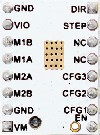
Pin Configuration and Descriptions
The TMC2100 is typically available in a 36-pin QFN package. Below is a summary of the key pins:
| Pin Name | Type | Description |
|---|---|---|
| V_M | Power | Motor power supply (4.75V to 46V). |
| V_IO | Power | Logic voltage supply (3.3V or 5V). |
| GND | Ground | Ground connection. |
| STEP | Input | Step signal input for controlling motor steps. |
| DIR | Input | Direction signal input for controlling motor rotation direction. |
| ENABLE | Input | Enables or disables the driver (active low). |
| MS1, MS2 | Input | Microstepping resolution selection pins. |
| DIAG | Output | Diagnostic output for stall detection or error reporting. |
| A1, A2 | Output | Motor coil A connections. |
| B1, B2 | Output | Motor coil B connections. |
| CFG1, CFG2 | Input | Configuration pins for setting driver modes (e.g., stealthChop, spreadCycle). |
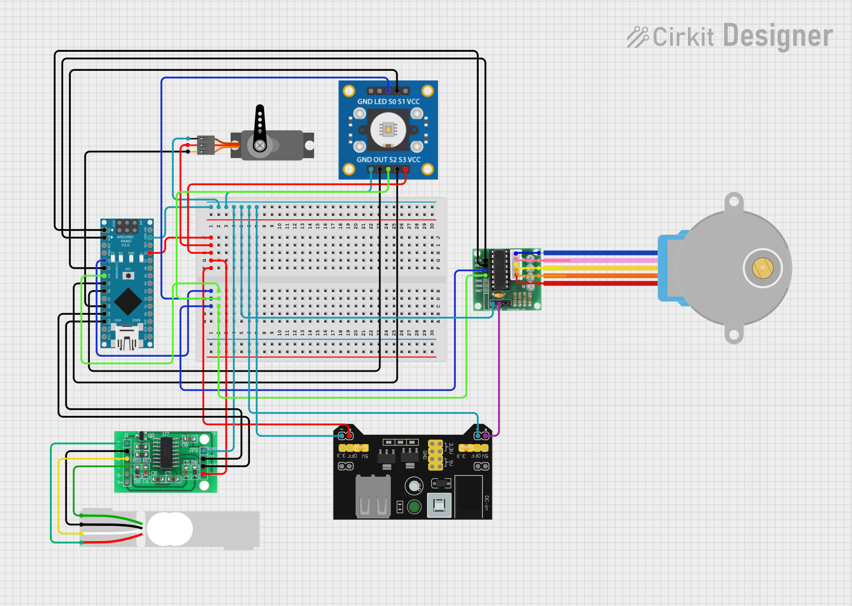
Usage Instructions
How to Use the TMC2100 in a Circuit
- Power Supply: Connect the motor power supply (V_M) to a voltage source between 4.75V and 46V. Ensure the logic voltage (V_IO) matches your microcontroller's logic level (3.3V or 5V).
- Motor Connections: Connect the stepper motor coils to the A1, A2, B1, and B2 pins. Ensure proper wiring to avoid incorrect motor operation.
- Control Signals:
- Connect the STEP pin to a microcontroller GPIO pin to send step pulses.
- Connect the DIR pin to a GPIO pin to control the motor's rotation direction.
- Use the ENABLE pin to enable or disable the driver.
- Microstepping Configuration: Use the MS1 and MS2 pins to set the desired microstepping resolution. Refer to the datasheet for the specific configuration table.
- Mode Selection: Configure the CFG1 and CFG2 pins to select the desired driver mode (e.g., stealthChop for quiet operation or spreadCycle for high torque).
- Bypass Capacitors: Place appropriate bypass capacitors (e.g., 100 µF and 0.1 µF) close to the V_M and V_IO pins to ensure stable operation.
Arduino UNO Example Code
Below is an example of how to control the TMC2100 with an Arduino UNO:
// Define pin connections
#define STEP_PIN 3  // Pin connected to STEP
#define DIR_PIN 4   // Pin connected to DIR
#define ENABLE_PIN 5 // Pin connected to ENABLE

void setup() {
  pinMode(STEP_PIN, OUTPUT);  // Set STEP pin as output
  pinMode(DIR_PIN, OUTPUT);   // Set DIR pin as output
  pinMode(ENABLE_PIN, OUTPUT); // Set ENABLE pin as output

  digitalWrite(ENABLE_PIN, LOW); // Enable the driver (active low)
  digitalWrite(DIR_PIN, HIGH);   // Set initial direction
}

void loop() {
  // Generate step pulses
  digitalWrite(STEP_PIN, HIGH);  // Set STEP pin high
  delayMicroseconds(500);        // Wait for 500 microseconds
  digitalWrite(STEP_PIN, LOW);   // Set STEP pin low
  delayMicroseconds(500);        // Wait for 500 microseconds
}
Important Considerations
- Heat Dissipation: The TMC2100 can generate significant heat during operation. Use a heatsink or ensure proper ventilation to prevent overheating.
- Current Limiting: Adjust the motor current using the reference voltage (V_REF) to avoid damaging the motor or driver.
- Noise Reduction: Use stealthChop mode for quiet operation, especially in noise-sensitive applications.
Troubleshooting and FAQs
Common Issues and Solutions
Motor Not Moving:
- Check the power supply connections (V_M and V_IO).
- Verify the STEP and DIR signals from the microcontroller.
- Ensure the ENABLE pin is set to the correct state (active low).
Overheating:
- Ensure proper heat dissipation with a heatsink or cooling fan.
- Reduce the motor current by adjusting the V_REF setting.
Noisy Operation:
- Enable stealthChop mode by configuring the CFG pins.
- Check for loose motor connections or improper wiring.
Stall Detection Not Working:
- Verify the DIAG pin connection and ensure the feature is enabled in the configuration.
FAQs
Q: Can the TMC2100 operate with a 12V power supply?
A: Yes, the TMC2100 supports a motor power supply voltage range of 4.75V to 46V, so 12V is within the acceptable range.
Q: How do I set the microstepping resolution?
A: Use the MS1 and MS2 pins to configure the microstepping resolution. Refer to the datasheet for the specific settings.
Q: What is the maximum current the TMC2100 can handle?
A: The TMC2100 can handle up to 1.2A RMS (2.5A peak) per motor coil. Ensure proper cooling to avoid overheating.
Q: Can I use the TMC2100 with a 5V logic microcontroller?
A: Yes, the TMC2100 supports both 3.3V and 5V logic levels for the V_IO pin.
By following this documentation, you can effectively integrate the TMC2100 into your projects for precise and efficient stepper motor control.