How to Use Adafruit Feather RP2040 RF95 LoRa Radio: Examples, Pinouts, and Specs
Introduction
The Adafruit Feather RP2040 RF95 LoRa Radio is a compact microcontroller board that combines the powerful RP2040 chip with an integrated LoRa RF95 radio module. This board is designed for long-range, low-power wireless communication, making it an excellent choice for Internet of Things (IoT) projects, remote sensing, and telemetry applications. Its small form factor and compatibility with the Feather ecosystem make it versatile and easy to integrate into a wide range of projects.
Explore Projects Built with Adafruit Feather RP2040 RF95 LoRa Radio

Explore Projects Built with Adafruit Feather RP2040 RF95 LoRa Radio
Common Applications and Use Cases
- IoT devices requiring long-range communication
- Environmental monitoring and remote sensing
- Smart agriculture and precision farming
- Asset tracking and geolocation systems
- Wireless sensor networks
- Low-power telemetry systems
Technical Specifications
Key Technical Details
- Microcontroller: RP2040 dual-core ARM Cortex-M0+ processor, running at 133 MHz
- Flash Memory: 8 MB (QSPI)
- RAM: 264 KB SRAM
- LoRa Radio Module: Semtech SX1276 (operating in the 868/915 MHz ISM band)
- Communication Range: Up to 2 km (line of sight, depending on environment)
- Power Supply: 3.3V logic, USB-C for power and programming
- Battery Support: JST connector for 3.7V LiPo battery
- GPIO Pins: 21 GPIO pins (3.3V logic)
- Interfaces: I2C, SPI, UART, ADC, PWM
- Dimensions: 51mm x 23mm x 8mm
- Weight: 5.5g
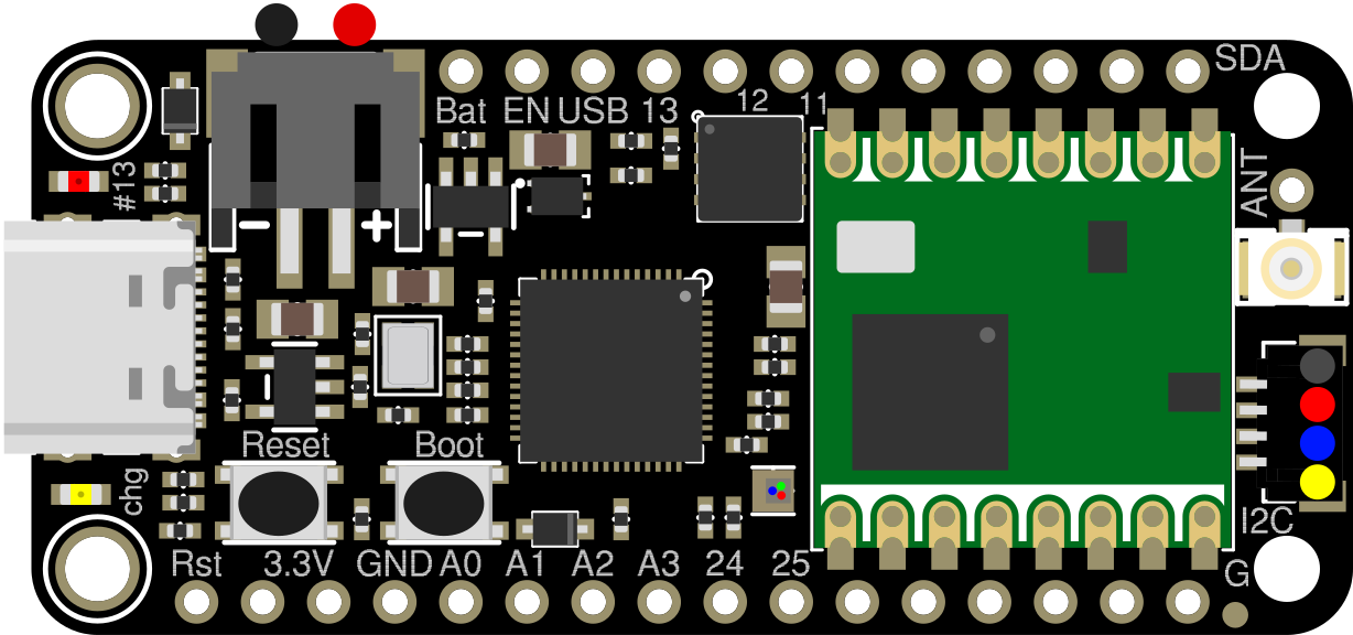
Pin Configuration and Descriptions
The Adafruit Feather RP2040 RF95 LoRa Radio has a standard Feather pinout. Below is a table describing the key pins:
| Pin | Function |
|---|---|
| USB | USB-C connector for power and programming |
| BAT | Battery input for 3.7V LiPo battery |
| 3V3 | 3.3V regulated output |
| GND | Ground |
| A0 - A5 | Analog input pins (can also be used as digital GPIO) |
| D0 - D13 | Digital GPIO pins (some support PWM and special functions) |
| SCL, SDA | I2C communication pins |
| SCK, MOSI, MISO | SPI communication pins |
| RX, TX | UART communication pins |
| RST | Reset pin |
| ANT | Antenna connection for the LoRa module |
| IRQ | Interrupt pin for the LoRa module |
| CS | Chip Select pin for the LoRa module |
Usage Instructions
How to Use the Component in a Circuit
Powering the Board:
- Connect the board to a USB-C cable for power and programming.
- Alternatively, connect a 3.7V LiPo battery to the BAT pin for portable operation.
Connecting the Antenna:
- Attach a compatible LoRa antenna to the ANT connector. Ensure the antenna matches the frequency band (868/915 MHz).
Programming the Board:
- Use the Arduino IDE or CircuitPython to program the board.
- Install the necessary board definitions and libraries (e.g., Adafruit RP2040 and RadioHead libraries).
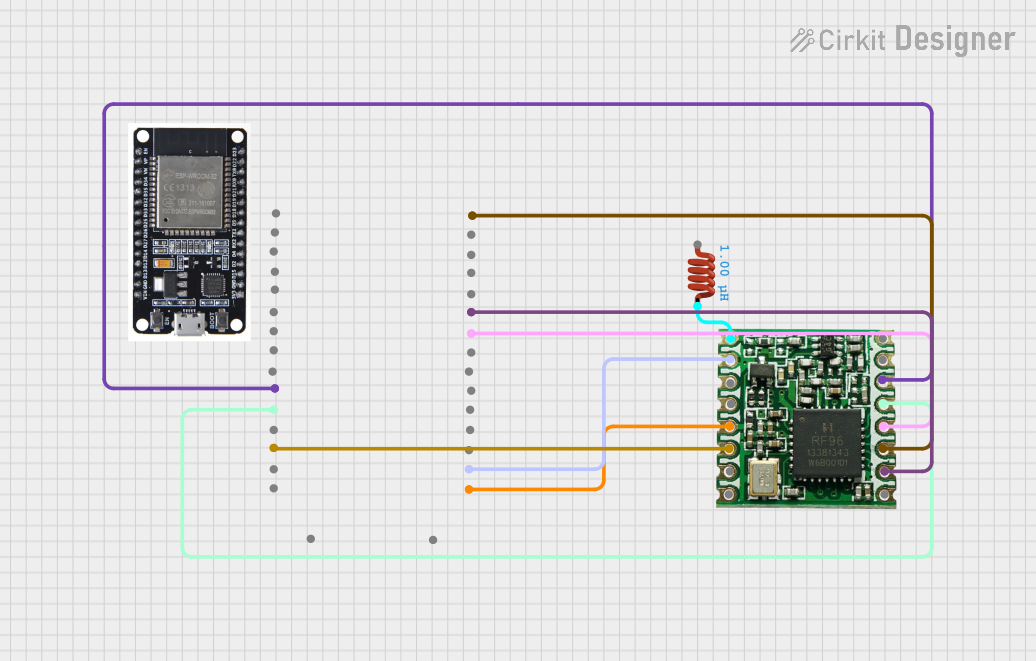
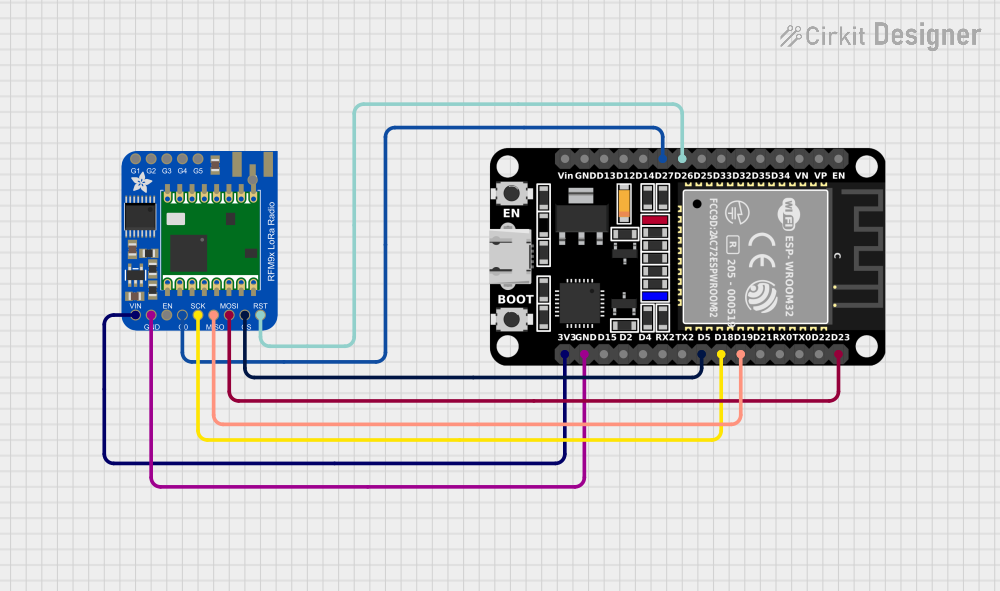
Interfacing with Peripherals:
- Use the GPIO pins to connect sensors, actuators, or other peripherals.
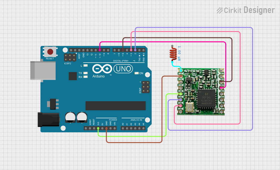
- For LoRa communication, connect the CS, IRQ, and SPI pins to the appropriate pins in your code.
Important Considerations and Best Practices
- Antenna Placement: Ensure the antenna is securely connected and positioned away from metal objects to maximize range.
- Power Supply: Use a stable power source to avoid communication issues. If using a battery, ensure it is adequately charged.
- Frequency Compliance: Verify that the LoRa frequency (868/915 MHz) complies with local regulations.
- Heat Management: Avoid placing the board in enclosed spaces without ventilation, as the RP2040 chip may generate heat during operation.
Example Code for Arduino UNO
Below is an example of how to send a simple LoRa message using the Adafruit Feather RP2040 RF95 LoRa Radio:
#include <SPI.h>
#include <RH_RF95.h>

// Define LoRa module pins
#define RFM95_CS 10  // Chip Select pin
#define RFM95_RST 9  // Reset pin
#define RFM95_INT 2  // Interrupt pin

// Frequency for LoRa communication (adjust based on your region)
#define RF95_FREQ 915.0

// Create an instance of the RF95 driver
RH_RF95 rf95(RFM95_CS, RFM95_INT);

void setup() {
  // Initialize serial communication
  Serial.begin(9600);
  while (!Serial);

  // Initialize LoRa module
  Serial.println("Initializing LoRa module...");
  pinMode(RFM95_RST, OUTPUT);
  digitalWrite(RFM95_RST, HIGH);
  delay(10);
  digitalWrite(RFM95_RST, LOW);
  delay(10);
  digitalWrite(RFM95_RST, HIGH);
  delay(10);

  if (!rf95.init()) {
    Serial.println("LoRa module initialization failed!");
    while (1);
  }

  // Set frequency
  if (!rf95.setFrequency(RF95_FREQ)) {
    Serial.println("Failed to set frequency!");
    while (1);
  }
  Serial.println("LoRa module initialized successfully.");
}

void loop() {
  // Send a test message
  Serial.println("Sending message...");
  const char *message = "Hello, LoRa!";
  rf95.send((uint8_t *)message, strlen(message));
  rf95.waitPacketSent();
  Serial.println("Message sent!");

  // Wait before sending the next message
  delay(5000);
}
Troubleshooting and FAQs
Common Issues and Solutions
LoRa Module Not Initializing:
- Ensure the CS, RST, and IRQ pins are correctly connected and defined in the code.
- Verify that the antenna is securely attached.
No Communication Between Devices:
- Check that both devices are set to the same frequency and spreading factor.
- Ensure the devices are within range and have a clear line of sight.
Board Not Recognized by Computer:
- Verify that the USB-C cable supports data transfer (not just charging).
- Check for proper installation of the RP2040 board drivers.
Low Signal Strength:
- Reposition the antenna to avoid obstructions.
- Use a higher-gain antenna if necessary.
FAQs
Can I use this board with CircuitPython?
Yes, the Adafruit Feather RP2040 RF95 LoRa Radio is fully compatible with CircuitPython.What is the maximum range of the LoRa module?
The range can reach up to 2 km in ideal conditions (line of sight).Can I power the board with a LiPo battery?
Yes, the board has a JST connector for a 3.7V LiPo battery.Is the board compatible with other FeatherWing add-ons?
Yes, the board follows the Feather standard and is compatible with most FeatherWings.