How to Use adxl345 keystudio: Examples, Pinouts, and Specs
Introduction
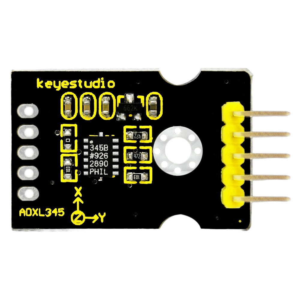
The ADXL345 KeyStudio is a small, thin, low-power, 3-axis accelerometer with high resolution (13-bit) measurement at up to ±16 g. Digital output data is formatted as 16-bit twos complement and is accessible through either a SPI (3- or 4-wire) or I2C digital interface. The ADXL345 is well-suited for mobile device applications. It can measure the static acceleration of gravity in tilt-sensing applications, as well as dynamic acceleration resulting from motion, shock, or vibration.
Explore Projects Built with adxl345 keystudio


Explore Projects Built with adxl345 keystudio
Common Applications and Use Cases
- Mobile device orientation detection (portrait/landscape)
- Gaming and pointing devices
- Impact and vibration detection
- Free-fall detection
- Real-time activity analysis
- Robotics
Technical Specifications
Key Technical Details
- Power Supply: 2.0V to 3.6V DC
- Interface: I2C, SPI (4-wire/3-wire)
- Sensing Range: ±2g, ±4g, ±8g, ±16g
- Resolution: 13-bit
- Output Data Rate: 0.1 Hz to 3200 Hz
Pin Configuration and Descriptions
| Pin Number | Name | Description |
|---|---|---|
| 1 | VCC | Power supply (2.0V to 3.6V) |
| 2 | GND | Ground |
| 3 | SCL/SPICLK | I2C clock line/SPI clock line |
| 4 | SDA/SDI | I2C data line/SPI data input |
| 5 | SDO | SPI data output (optional) |
| 6 | CS | SPI chip select (active low) |
| 7 | INT1 | Interrupt output 1 |
| 8 | INT2 | Interrupt output 2 |
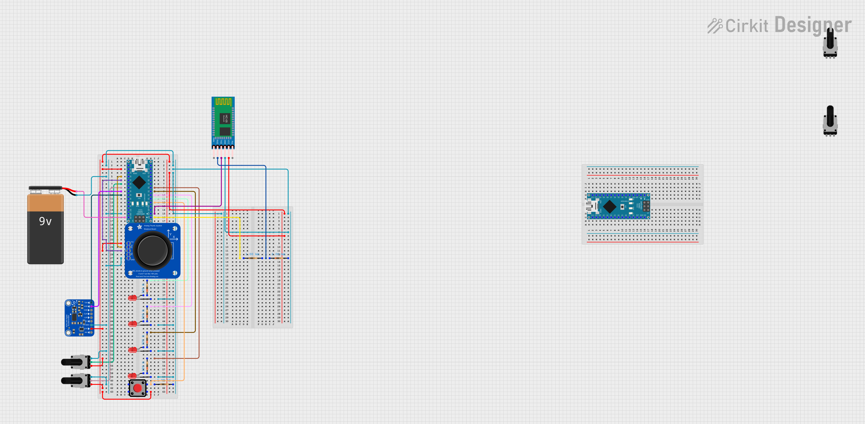
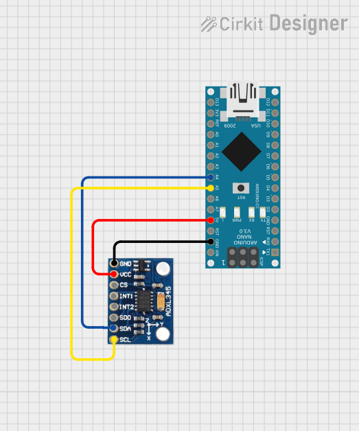
Usage Instructions
How to Use the Component in a Circuit
- Powering the Module: Connect VCC to a 2.0V to 3.6V power supply and GND to the ground of your system.
- Interface Selection:
- For I2C, connect SCL to the I2C clock and SDA to the I2C data.
- For SPI, connect SPICLK to the SPI clock, SDI to the SPI data input, SDO to the SPI data output (if needed), and CS to the chip select.
- Setting Up Interrupts (Optional): Connect INT1 and/or INT2 to the microcontroller interrupt pins if you plan to use the interrupt features.
Important Considerations and Best Practices
- Ensure that the power supply is within the specified range to prevent damage.
- Use pull-up resistors on the I2C lines if they are not already present on the microcontroller board.
- When using SPI, ensure that the CS pin is set to a high state when the device is not in use.
- For accurate readings, the sensor should be mounted on a stable surface without vibrations.
Example Code for Arduino UNO
#include <Wire.h>
#include <ADXL345.h>

ADXL345 adxl; // Create an instance of the ADXL345 library

void setup() {
  Wire.begin();        // Join I2C bus
  Serial.begin(9600);  // Initialize serial communication
  adxl.initADXL345();  // Initialize the ADXL345
}

void loop() {
  int x, y, z;
  adxl.readAccel(&x, &y, &z); // Read the accelerometer values
  // Output the values to the serial monitor
  Serial.print("x: ");
  Serial.print(x);
  Serial.print(" y: ");
  Serial.print(y);
  Serial.print(" z: ");
  Serial.println(z);
  delay(100); // Delay for readability
}
Troubleshooting and FAQs
Common Issues Users Might Face
- No Data Output: Ensure that the power supply is connected correctly and the I2C/SPI lines are properly configured.
- Inaccurate Readings: Check that the sensor is not subject to vibrations or other external forces. Calibrate the sensor if necessary.
- Communication Errors: Verify that the pull-up resistors are in place for I2C. For SPI, ensure that the CS pin is being managed correctly.
Solutions and Tips for Troubleshooting
- Power Supply Issues: Use a multimeter to check the voltage at the VCC pin.
- Connection Problems: Double-check wiring against the pin configuration table.
- Code Debugging: Add serial print statements to confirm that the program is running as expected and to check the values being read.
FAQs
Q: Can the ADXL345 KeyStudio be used with both 3.3V and 5V microcontrollers? A: Yes, but ensure that the VCC is within the specified range and logic level conversion is used if necessary.
Q: How can I change the range of measurement? A: The range can be set using the appropriate function in the library. Refer to the library documentation for details.
Q: What is the purpose of the INT1 and INT2 pins? A: These pins can be configured to trigger interrupts for events like free-fall, activity/inactivity, and more.
Q: How do I calibrate the ADXL345? A: Calibration involves setting offsets for the x, y, and z axes using the library functions after placing the sensor in a known orientation.
Q: Can I use multiple ADXL345 sensors on the same I2C bus? A: Yes, the ADXL345 has an alternate I2C address that can be used by connecting the SDO pin to VCC. This allows for two sensors on the same I2C bus.