How to Use esp-12s: Examples, Pinouts, and Specs
Introduction
The ESP-12S is a Wi-Fi module manufactured by Guest, with the part ID ESP-12S_NOTE. It is based on the ESP8266 chip and features built-in Wi-Fi capabilities, GPIO pins, and support for various communication protocols. This module is widely used in Internet of Things (IoT) applications, enabling devices to connect seamlessly to the internet.
Explore Projects Built with esp-12s

Explore Projects Built with esp-12s
Common Applications and Use Cases
- Smart home devices (e.g., smart plugs, lights, and thermostats)
- IoT sensors and data loggers
- Wireless communication for embedded systems
- Remote monitoring and control systems
- Prototyping and development of Wi-Fi-enabled projects
Technical Specifications
The ESP-12S is a compact and powerful module with the following key specifications:
| Parameter | Value |
|---|---|
| Chipset | ESP8266 |
| Wi-Fi Standard | IEEE 802.11 b/g/n |
| Operating Voltage | 3.0V to 3.6V |
| Flash Memory | 4 MB (32 Mbit) |
| GPIO Pins | 11 (multiplexed for UART, SPI, I2C, PWM, etc.) |
| Operating Temperature | -40°C to +125°C |
| Power Consumption | 20 mA (standby), 170 mA (transmit mode) |
| Dimensions | 16 mm x 24 mm |
| Antenna | PCB antenna (onboard) |
| Communication Protocols | UART, SPI, I2C, PWM, GPIO |
| Maximum Wi-Fi Speed | 72.2 Mbps |
| Security Features | WPA/WPA2 encryption, WEP, TKIP, AES |
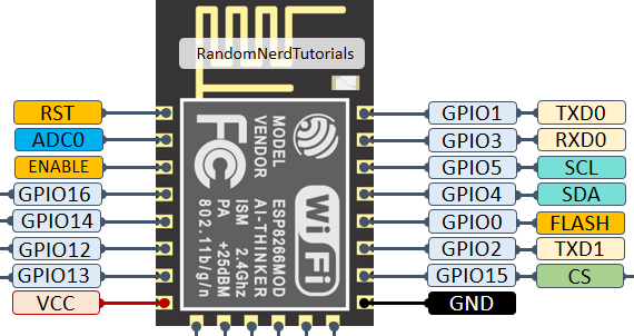
Pin Configuration and Descriptions
The ESP-12S module has 16 pins, with the following configuration:
| Pin Number | Pin Name | Description |
|---|---|---|
| 1 | GND | Ground connection |
| 2 | GPIO16 | General-purpose I/O pin |
| 3 | GPIO14 | General-purpose I/O pin (HSPI_CLK) |
| 4 | GPIO12 | General-purpose I/O pin (HSPI_MISO) |
| 5 | GPIO13 | General-purpose I/O pin (HSPI_MOSI, UART0_CTS) |
| 6 | GPIO15 | General-purpose I/O pin (HSPI_CS, UART0_RTS) |
| 7 | GPIO2 | General-purpose I/O pin |
| 8 | GPIO0 | General-purpose I/O pin (used for boot mode selection) |
| 9 | GPIO4 | General-purpose I/O pin |
| 10 | GPIO5 | General-purpose I/O pin |
| 11 | RXD | UART0 receive pin |
| 12 | TXD | UART0 transmit pin |
| 13 | CH_PD | Chip enable (active high, must be pulled high for normal operation) |
| 14 | VCC | Power supply input (3.3V) |
| 15 | RST | Reset pin (active low) |
| 16 | GND | Ground connection |
Usage Instructions
How to Use the ESP-12S in a Circuit
- Power Supply: Provide a stable 3.3V power supply to the VCC pin. Ensure that the power source can supply sufficient current (at least 300 mA) for reliable operation.
- Enable the Module: Connect the CH_PD pin to 3.3V to enable the module. This pin must remain high during operation.
- Boot Mode Selection: Use GPIO0 to select the boot mode:
- Pull GPIO0 to GND for firmware flashing.
- Pull GPIO0 to 3.3V for normal operation.
- Connect to a Microcontroller: Use the RXD and TXD pins to establish UART communication with a microcontroller (e.g., Arduino UNO).
- Antenna Placement: Ensure that the onboard PCB antenna is not obstructed by metal objects or enclosures to maintain optimal Wi-Fi performance.
Important Considerations and Best Practices
- Level Shifting: The ESP-12S operates at 3.3V logic levels. If connecting to a 5V microcontroller, use a level shifter to avoid damaging the module.
- Decoupling Capacitors: Place a 10 µF and a 0.1 µF capacitor near the VCC pin to stabilize the power supply.
- Firmware Updates: Use the UART interface to flash firmware updates. Ensure GPIO0 is pulled low during the flashing process.
- Heat Dissipation: Avoid placing the module in enclosed spaces without proper ventilation, as it may generate heat during operation.
Example: Connecting ESP-12S to Arduino UNO
Below is an example of how to connect the ESP-12S to an Arduino UNO and send AT commands to control the module.
Wiring Diagram
| ESP-12S Pin | Arduino UNO Pin |
|---|---|
| VCC | 3.3V |
| GND | GND |
| RXD | TX (via 3.3V level shifter) |
| TXD | RX (via 3.3V level shifter) |
| CH_PD | 3.3V |
| GPIO0 | 3.3V (normal mode) |
Arduino Code
#include <SoftwareSerial.h>

// Define RX and TX pins for SoftwareSerial
SoftwareSerial espSerial(2, 3); // RX = Pin 2, TX = Pin 3

void setup() {
  Serial.begin(9600); // Initialize hardware serial for debugging
  espSerial.begin(115200); // Initialize ESP-12S communication

  Serial.println("ESP-12S Test");
  delay(1000);

  // Send AT command to test communication
  espSerial.println("AT");
}

void loop() {
  // Check if ESP-12S sends data
  if (espSerial.available()) {
    String response = espSerial.readString();
    Serial.println("ESP-12S Response: " + response);
  }

  // Check if user sends data via Serial Monitor
  if (Serial.available()) {
    String command = Serial.readString();
    espSerial.println(command); // Send command to ESP-12S
  }
}
Troubleshooting and FAQs
Common Issues and Solutions
Module Not Responding to AT Commands
- Ensure the CH_PD pin is connected to 3.3V.
- Verify the baud rate (default is 115200).
- Check wiring connections, especially RX and TX pins.
Wi-Fi Connection Fails
- Ensure the correct SSID and password are used.
- Check for interference from other Wi-Fi networks or devices.
- Verify that the module is within range of the Wi-Fi router.
Overheating
- Ensure proper ventilation around the module.
- Avoid prolonged operation at maximum transmission power.
Flashing Firmware Fails
- Confirm that GPIO0 is pulled low during the flashing process.
- Use a reliable USB-to-serial adapter with sufficient current supply.
FAQs
Q: Can the ESP-12S operate at 5V?
A: No, the ESP-12S operates at 3.3V. Connecting it to 5V may damage the module.
Q: How do I reset the module?
A: Pull the RST pin low momentarily to reset the module.
Q: Can I use the ESP-12S without a microcontroller?
A: Yes, the ESP-12S can be programmed directly using the ESP8266 SDK or Arduino IDE.