How to Use Door contact: Examples, Pinouts, and Specs
Introduction
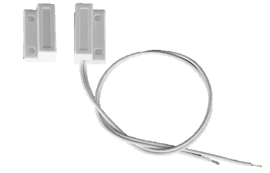
A door contact is a security device used to detect the open or closed state of a door. It typically consists of two parts: a magnet and a reed switch. When the door is closed, the magnet aligns with the reed switch, keeping the circuit closed. When the door opens, the magnet moves away, causing the reed switch to open the circuit and send a signal. Door contacts are widely used in security systems, home automation, and access control systems.
Explore Projects Built with Door contact
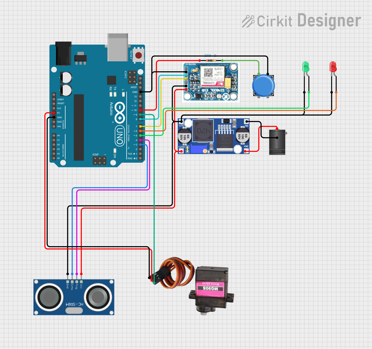
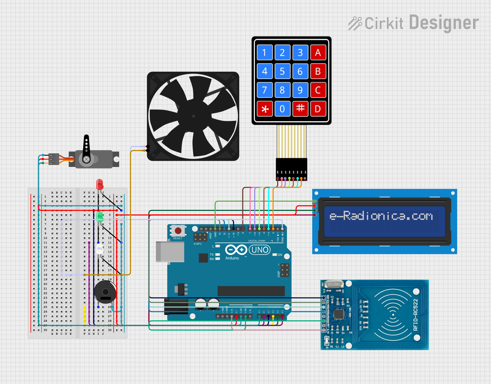

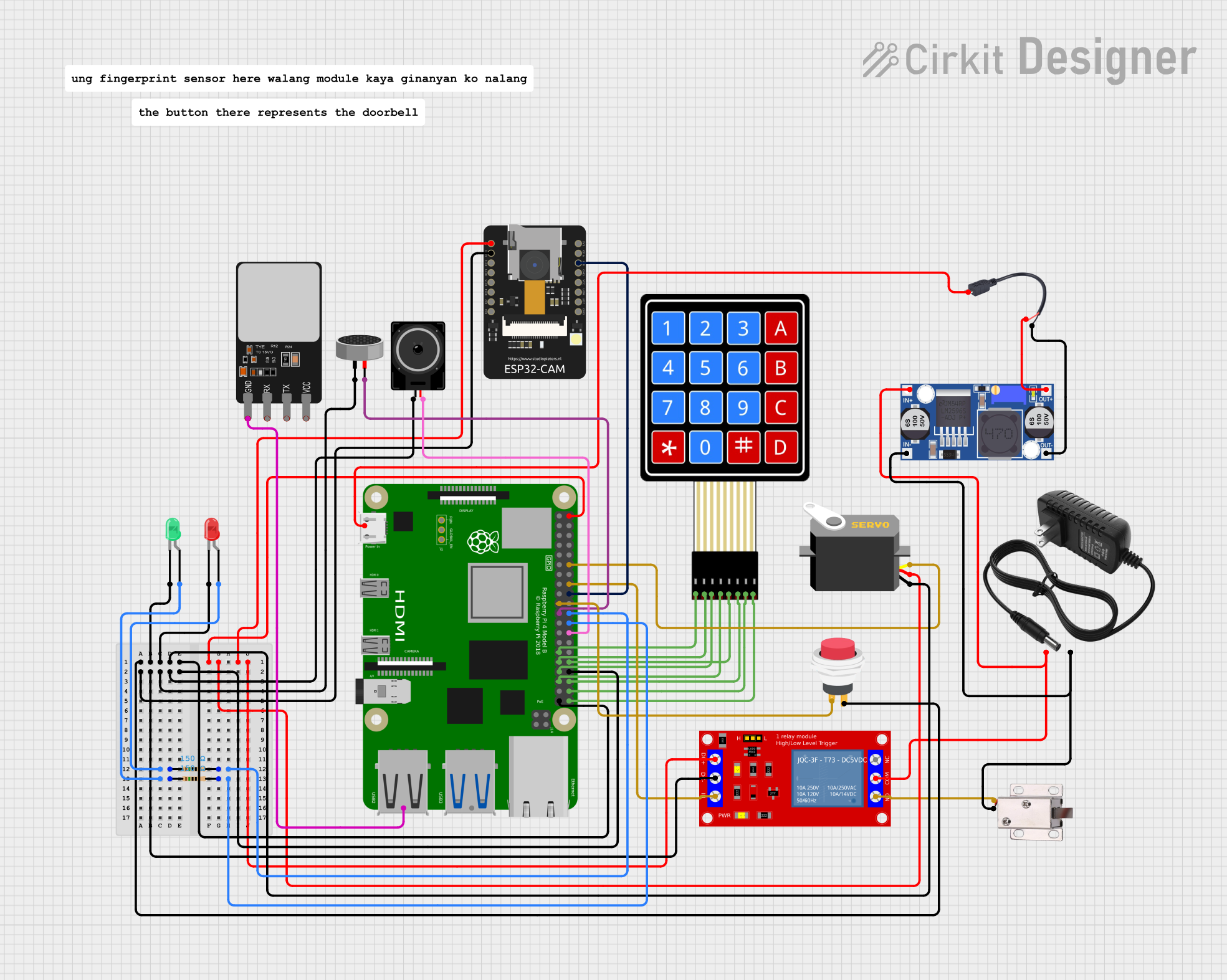
Explore Projects Built with Door contact
Common Applications and Use Cases
- Intrusion detection in security systems
- Monitoring door status in smart home automation
- Triggering alarms or notifications when a door is opened
- Controlling lighting or HVAC systems based on door status
- Industrial applications for monitoring access to restricted areas
Technical Specifications
Below are the typical technical specifications for a standard door contact:
| Parameter | Value |
|---|---|
| Operating Voltage | 3V to 24V DC |
| Contact Type | Normally Open (NO) or Normally Closed (NC) |
| Contact Rating | 500mA at 12V DC |
| Operating Distance | 10mm to 25mm (depending on model) |
| Housing Material | ABS plastic or similar durable material |
| Mounting Type | Surface-mounted or recessed |
| Operating Temperature | -20°C to 50°C |
Pin Configuration and Descriptions
Door contacts typically do not have pins but instead use two wires for connection. The wiring details are as follows:
| Wire Color | Description |
|---|---|
| Red/White | Signal wire (connects to the input of the monitoring device) |
| Black | Ground wire (connects to the ground of the monitoring device) |
Usage Instructions
How to Use the Component in a Circuit
Mounting the Door Contact:
- Attach the reed switch to the stationary part of the door frame.
- Mount the magnet on the moving part of the door, ensuring alignment with the reed switch when the door is closed.
Wiring the Door Contact:
- Connect the signal wire (red/white) to the input pin of your monitoring device (e.g., microcontroller or alarm system).
- Connect the ground wire (black) to the ground terminal of the monitoring device.
Testing the Circuit:
- Power the circuit and monitor the input signal.
- When the door is closed, the circuit should remain in its default state (closed for NC or open for NO).
- When the door opens, the circuit state should change, triggering the desired action (e.g., alarm or notification).
Important Considerations and Best Practices
- Ensure proper alignment between the magnet and reed switch for reliable operation.
- Use appropriate pull-up or pull-down resistors if connecting to a microcontroller.
- Avoid placing the door contact near strong magnetic fields, as this may interfere with its operation.
- Use shielded cables for long wiring runs to minimize electrical noise.
Example: Connecting to an Arduino UNO
Below is an example of how to connect and use a Normally Open (NO) door contact with an Arduino UNO:
Circuit Diagram
- Connect the signal wire of the door contact to digital pin 2 on the Arduino.
- Connect the ground wire of the door contact to the GND pin on the Arduino.
- Use a 10kΩ pull-down resistor between digital pin 2 and GND.
Arduino Code
// Define the pin connected to the door contact
const int doorContactPin = 2;

// Variable to store the door status
int doorStatus = 0;

void setup() {
  // Initialize the door contact pin as an input
  pinMode(doorContactPin, INPUT);

  // Start the serial communication for debugging
  Serial.begin(9600);
}

void loop() {
  // Read the state of the door contact
  doorStatus = digitalRead(doorContactPin);

  // Check if the door is open or closed
  if (doorStatus == HIGH) {
    // Door is open
    Serial.println("Door is OPEN");
  } else {
    // Door is closed
    Serial.println("Door is CLOSED");
  }

  // Add a small delay to avoid spamming the serial monitor
  delay(500);
}
Troubleshooting and FAQs
Common Issues Users Might Face
Door contact not triggering correctly:
- Cause: Misalignment between the magnet and reed switch.
- Solution: Adjust the position of the magnet and reed switch to ensure proper alignment.
False triggers or noise in the signal:
- Cause: Electrical noise or long wiring runs.
- Solution: Use shielded cables and add a pull-up or pull-down resistor to stabilize the signal.
No response from the monitoring device:
- Cause: Incorrect wiring or damaged components.
- Solution: Double-check the wiring and test the door contact with a multimeter to ensure it is functioning.
Door contact works intermittently:
- Cause: Loose connections or environmental factors (e.g., temperature changes).
- Solution: Secure all connections and ensure the device is operating within its specified temperature range.
FAQs
Q: Can I use a door contact with an AC-powered system?
A: Most door contacts are designed for low-voltage DC systems. If you need to use it with an AC system, ensure the contact rating supports it or use a relay to interface with the AC circuit.
Q: What is the difference between Normally Open (NO) and Normally Closed (NC) contacts?
A: A Normally Open (NO) contact remains open (no current flows) when the door is closed and closes (current flows) when the door opens. A Normally Closed (NC) contact behaves oppositely, remaining closed when the door is closed and opening when the door opens.
Q: Can I use a door contact outdoors?
A: Standard door contacts are not weatherproof. For outdoor use, choose a weatherproof model or install the device in a protected enclosure.
Q: How do I extend the wire length for a door contact?
A: Use shielded cables to minimize electrical noise and ensure secure connections to prevent signal loss.