How to Use Adafruit Micro USB Breakout: Examples, Pinouts, and Specs
Introduction
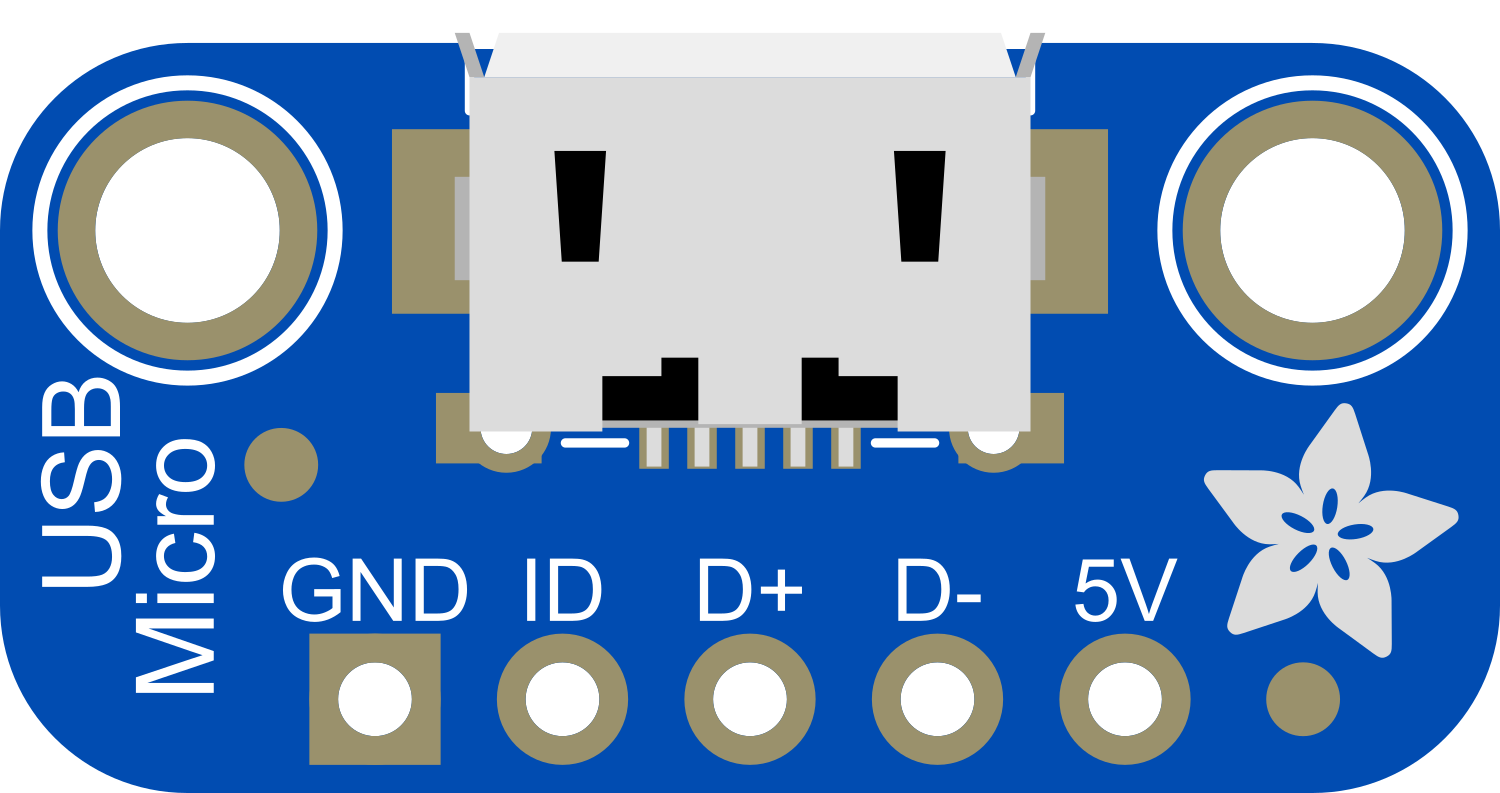
The Adafruit Micro USB Breakout board is a compact and versatile component that simplifies the integration of a micro USB connector into any electronic project. This breakout board is particularly useful for providing power to custom circuit boards, interfacing with computers or other USB devices, and for projects that require a USB connection for programming or communication purposes.
Explore Projects Built with Adafruit Micro USB Breakout

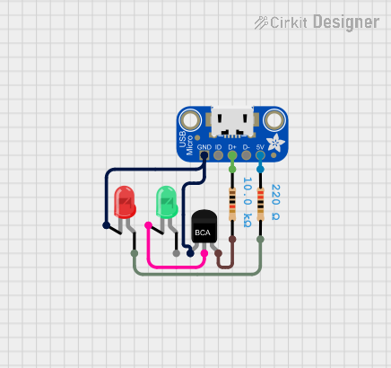
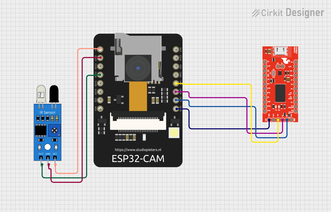

Explore Projects Built with Adafruit Micro USB Breakout
Common Applications and Use Cases
- Power supply for microcontroller boards
- USB connectivity for data transfer
- Charging batteries in portable devices
- Prototyping USB devices
- Adding a USB interface to custom projects
Technical Specifications
Key Technical Details
- Connector Type: Micro USB Type B
- Operating Voltage: 5V (typical USB power)
- Maximum Current: According to USB 2.0 specifications
Pin Configuration and Descriptions
| Pin Number | Name | Description |
|---|---|---|
| 1 | VBUS | +5V from USB |
| 2 | D- | USB Data - |
| 3 | D+ | USB Data + |
| 4 | ID | Not connected (typically used for OTG) |
| 5 | GND | Ground connection |
Usage Instructions
How to Use the Component in a Circuit
- Soldering Wires: Begin by soldering wires to the breakout board's pads. Ensure a good solder joint for reliable connections.
- Power Connection: Connect the VBUS pad to the +5V input on your circuit and the GND pad to the ground plane.
- Data Connection: If data transfer is required, connect the D+ and D- pads to the appropriate data lines on your microcontroller or USB interface chip.
Important Considerations and Best Practices
- Power Rating: Do not exceed the USB 2.0 power specifications; ensure your device's power consumption is within the limits.
- Data Lines: Use twisted-pair wires for D+ and D- to reduce noise and maintain signal integrity.
- Mounting: Secure the breakout board to your project enclosure or PCB to prevent movement and potential disconnections.
- ESD Precautions: Handle the breakout board with care to avoid electrostatic discharge damage.
Example Code for Arduino UNO
// This example demonstrates how to power an Arduino UNO using the Adafruit Micro USB Breakout Board.

void setup() {
  // Initialize the Serial communication at 9600 baud rate.
  Serial.begin(9600);
}

void loop() {
  // Send a message to the Serial Monitor.
  Serial.println("Powered by Adafruit Micro USB Breakout Board");
  // Wait for a second.
  delay(1000);
}
Troubleshooting and FAQs
Common Issues
- No Power: Ensure that the micro USB cable is properly connected and that the power source (e.g., computer USB port) is on.
- Intermittent Connection: Check for loose solder joints or wires. Also, ensure the micro USB cable is not damaged.
- Data Transfer Not Working: Verify that the D+ and D- lines are correctly connected and that there are no shorts or open circuits.
Solutions and Tips for Troubleshooting
- Soldering: If new to soldering, practice on spare components to ensure quality connections.
- Cable Quality: Use a high-quality micro USB cable to ensure a stable connection.
- Power Source: If using a computer USB port, ensure it can provide sufficient current for your project.
FAQs
Q: Can I use this breakout board for USB OTG applications? A: The ID pin is not connected on this breakout board, which is typically used for USB OTG signaling, so it may not be suitable for such applications without modification.
Q: Is it possible to use this breakout board for USB 3.0 applications? A: No, this breakout board is designed for USB 2.0 applications and does not support the additional connections required for USB 3.0.
Q: How much current can the breakout board handle? A: The breakout board can handle the standard current provided by a USB 2.0 port, which is up to 500mA for high-power devices. Ensure your project's current draw does not exceed this limit.