How to Use 5V-12V to 3.3V Fixed Output DC-DC Step-Down Buck : Examples, Pinouts, and Specs
Introduction
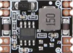
The 5V-12V to 3.3V Fixed Output DC-DC Step-Down Buck Converter is a compact and efficient power regulation module designed to step down input voltages ranging from 5V to 12V to a stable 3.3V output. This component is widely used in low-voltage applications where a reliable 3.3V power supply is required, such as powering microcontrollers, sensors, and other electronic devices.
Explore Projects Built with 5V-12V to 3.3V Fixed Output DC-DC Step-Down Buck


Explore Projects Built with 5V-12V to 3.3V Fixed Output DC-DC Step-Down Buck
Common Applications and Use Cases
- Powering 3.3V microcontrollers (e.g., ESP8266, ESP32)
- Supplying power to low-voltage sensors and modules
- Battery-powered devices requiring efficient voltage regulation
- Embedded systems and IoT applications
Technical Specifications
The following table outlines the key technical details of the 5V-12V to 3.3V DC-DC Step-Down Buck Converter:
| Parameter | Value |
|---|---|
| Input Voltage Range | 5V to 12V |
| Output Voltage | 3.3V (fixed) |
| Output Current | Up to 800mA (varies by input) |
| Efficiency | Up to 92% (depending on load) |
| Switching Frequency | 150 kHz |
| Operating Temperature | -40°C to +85°C |
| Dimensions | Typically 22mm x 17mm x 4mm |
Pin Configuration and Descriptions
The module typically has three pins or solder pads for connection. The table below describes each pin:
| Pin Name | Description |
|---|---|
| VIN | Input voltage pin (connect to 5V-12V power source) |
| GND | Ground pin (common ground for input and output) |
| VOUT | Output voltage pin (provides regulated 3.3V output) |
Usage Instructions
How to Use the Component in a Circuit
Connect the Input Voltage (VIN):
Attach the VIN pin to a power source that provides a voltage between 5V and 12V. Ensure the power source can supply sufficient current for your application.Connect the Ground (GND):
Connect the GND pin to the ground of your circuit. This is the common ground for both input and output.Connect the Output Voltage (VOUT):
Attach the VOUT pin to the device or circuit requiring a 3.3V power supply. Ensure the load does not exceed the maximum output current (800mA).Verify Connections:
Double-check all connections before powering the circuit to avoid damage to the module or connected devices.
Important Considerations and Best Practices
- Input Voltage Range: Ensure the input voltage remains within the specified range (5V-12V). Exceeding this range may damage the module.
- Heat Dissipation: For higher loads, the module may generate heat. Ensure adequate ventilation or consider adding a heatsink if necessary.
- Load Current: Do not exceed the maximum output current (800mA). Overloading the module can cause instability or permanent damage.
- Decoupling Capacitors: For improved stability, consider adding a 10µF capacitor across the input and output terminals.
Example: Using with an Arduino UNO
The 5V-12V to 3.3V Step-Down Buck Converter can be used to power 3.3V sensors or modules in an Arduino project. Below is an example of how to connect the module:
- Connect the VIN pin of the module to the 5V pin of the Arduino UNO.
- Connect the GND pin of the module to the GND pin of the Arduino UNO.
- Connect the VOUT pin of the module to the 3.3V sensor or module.
Here is a simple Arduino code example for reading data from a 3.3V sensor (e.g., a DHT11 temperature and humidity sensor):
#include <DHT.h>

// Define the DHT sensor type and pin
#define DHTPIN 2      // DHT sensor connected to digital pin 2
#define DHTTYPE DHT11 // DHT11 sensor type

DHT dht(DHTPIN, DHTTYPE);

void setup() {
  Serial.begin(9600); // Initialize serial communication
  dht.begin();        // Initialize the DHT sensor
}

void loop() {
  // Read temperature and humidity from the DHT sensor
  float humidity = dht.readHumidity();
  float temperature = dht.readTemperature();

  // Check if the readings are valid
  if (isnan(humidity) || isnan(temperature)) {
    Serial.println("Failed to read from DHT sensor!");
    return;
  }

  // Print the readings to the Serial Monitor
  Serial.print("Humidity: ");
  Serial.print(humidity);
  Serial.print("%  Temperature: ");
  Serial.print(temperature);
  Serial.println("°C");

  delay(2000); // Wait 2 seconds before the next reading
}
Note: The 5V-12V to 3.3V Step-Down Buck Converter ensures the sensor receives a stable 3.3V supply, even if the Arduino operates at 5V.
Troubleshooting and FAQs
Common Issues Users Might Face
No Output Voltage:
- Cause: Incorrect wiring or insufficient input voltage.
- Solution: Verify that the VIN and GND pins are correctly connected to a power source within the 5V-12V range.
Overheating:
- Cause: Excessive load current or poor ventilation.
- Solution: Reduce the load current or improve heat dissipation by adding a heatsink or ensuring proper airflow.
Output Voltage Instability:
- Cause: Insufficient decoupling or noisy input power.
- Solution: Add a 10µF capacitor across the input and output terminals to stabilize the voltage.
Device Not Powering On:
- Cause: Load exceeds the maximum output current.
- Solution: Ensure the connected device draws less than 800mA.
FAQs
Q: Can I use this module with a 12V car battery?
A: Yes, the module can step down a 12V car battery's voltage to 3.3V. However, ensure the load does not exceed the module's maximum output current.
Q: Is the output voltage adjustable?
A: No, this module provides a fixed 3.3V output and cannot be adjusted.
Q: Can I use this module to power an ESP32?
A: Yes, the module is suitable for powering an ESP32, as it requires a stable 3.3V supply. Ensure the input voltage is within the specified range.
Q: What happens if I connect a load that exceeds 800mA?
A: Exceeding the maximum output current may cause the module to overheat, become unstable, or fail permanently. Always ensure the load is within the specified limits.