How to Use GPS GY-NEO6MV2: Examples, Pinouts, and Specs
Introduction
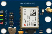
The GPS GY-NEO6MV2 is a compact and reliable GPS module manufactured by Ublox, with the part ID 180943. It is built around the NEO-6M GPS chip, which provides accurate positioning data. This module is widely used in applications such as robotics, navigation systems, drones, and IoT devices requiring precise location tracking. Its small form factor and ease of integration make it a popular choice for both hobbyists and professionals.
Explore Projects Built with GPS GY-NEO6MV2


Explore Projects Built with GPS GY-NEO6MV2
Technical Specifications
The GPS GY-NEO6MV2 module is designed to deliver high performance in a variety of environments. Below are its key technical details:
Key Specifications
| Parameter | Value |
|---|---|
| Chipset | Ublox NEO-6M |
| Input Voltage | 3.3V to 5V |
| Operating Current | 45mA (typical) |
| Positioning Accuracy | 2.5 meters CEP (Circular Error Probable) |
| Communication Interface | UART (default baud rate: 9600) |
| Antenna | External active antenna (included) |
| Backup Battery | CR1220 (for saving configuration) |
| Operating Temperature | -40°C to +85°C |
| Dimensions | 25mm x 35mm |
Pin Configuration
The GPS GY-NEO6MV2 module has a 4-pin interface for easy connection. Below is the pinout description:
| Pin Name | Pin Number | Description |
|---|---|---|
| VCC | 1 | Power input (3.3V to 5V) |
| GND | 2 | Ground |
| TX | 3 | UART Transmit (data output) |
| RX | 4 | UART Receive (data input) |
Usage Instructions
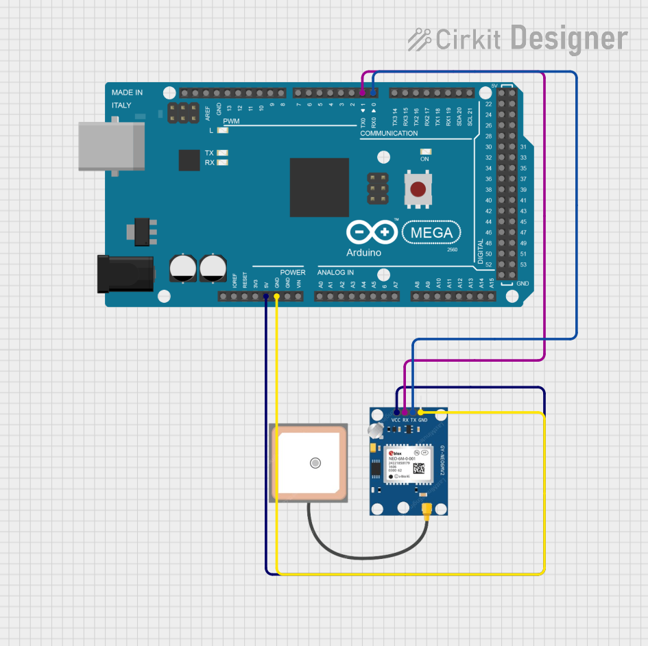
How to Use the GPS GY-NEO6MV2 in a Circuit
- Power Supply: Connect the VCC pin to a 3.3V or 5V power source and the GND pin to ground.
- UART Communication: Connect the TX pin of the module to the RX pin of your microcontroller (e.g., Arduino UNO) and the RX pin of the module to the TX pin of the microcontroller.
- Antenna: Ensure the external active antenna is securely connected to the module for optimal GPS signal reception.
- Backup Battery: Insert a CR1220 battery into the module's battery holder to retain configuration settings when the module is powered off.
Important Considerations and Best Practices
- Place the GPS module in an open area with a clear view of the sky for the best signal reception.
- Avoid placing the module near sources of electromagnetic interference (e.g., motors, power supplies).
- Use a level shifter if interfacing the module with a 3.3V microcontroller to avoid damaging the RX pin.
- Allow the module a few minutes to acquire satellite signals during the first use or after a long period of inactivity.
Example Code for Arduino UNO
Below is an example code to interface the GPS GY-NEO6MV2 module with an Arduino UNO and display GPS data on the Serial Monitor:
#include <SoftwareSerial.h>

// Define RX and TX pins for SoftwareSerial
SoftwareSerial gpsSerial(4, 3); // RX = Pin 4, TX = Pin 3

void setup() {
  Serial.begin(9600);          // Initialize Serial Monitor at 9600 baud
  gpsSerial.begin(9600);       // Initialize GPS module at 9600 baud
  Serial.println("GPS Module Initialized");
}

void loop() {
  while (gpsSerial.available()) {
    char gpsData = gpsSerial.read(); // Read data from GPS module
    Serial.print(gpsData);           // Print GPS data to Serial Monitor
  }
}
Note: Ensure the RX and TX pins in the code match the pins you use on the Arduino UNO. The GPS module's default baud rate is 9600, but it can be configured if needed.
Troubleshooting and FAQs
Common Issues and Solutions
No GPS Data Received:
- Ensure the module is powered correctly (check VCC and GND connections).
- Verify the TX and RX connections between the GPS module and the microcontroller.
- Check that the antenna is securely connected and positioned in an open area.
Poor Signal Reception:
- Move the module to a location with a clear view of the sky.
- Avoid placing the module near metal objects or electronic devices that may cause interference.
Incorrect Data Format:
- Ensure the baud rate of the GPS module matches the baud rate in your code.
- Use a GPS parsing library (e.g., TinyGPS++ for Arduino) to decode NMEA sentences into readable data.
FAQs
Q: Can the GPS GY-NEO6MV2 module work indoors?
A: While the module may work indoors, signal reception is significantly reduced. For best results, use the module outdoors or near a window.
Q: How long does it take to acquire a GPS fix?
A: The time to acquire a fix depends on the environment. A cold start (first use) may take up to 30 seconds to a few minutes, while a warm start (recent use) typically takes a few seconds.
Q: Can I change the default baud rate of the module?
A: Yes, the baud rate can be changed using Ublox's u-center software or by sending specific configuration commands to the module.
Q: What is the purpose of the backup battery?
A: The backup battery retains the module's configuration and satellite data, reducing the time required for a GPS fix after power loss.
By following this documentation, you can effectively integrate and use the GPS GY-NEO6MV2 module in your projects.