Cirkit Designer Logo
Cirkit Designer
Your all-in-one circuit design IDE
Home / 
Component Documentation

How to Use SparkFun LiPo Charger Basic - Micro-USB: Examples, Pinouts, and Specs

Image of SparkFun LiPo Charger Basic - Micro-USB
Cirkit Designer LogoDesign with SparkFun LiPo Charger Basic - Micro-USB in Cirkit Designer

Introduction

The SparkFun LiPo Charger Basic - Micro-USB is a compact and easy-to-use charging solution for Lithium Polymer (LiPo) batteries. This component is designed to charge single-cell LiPo batteries with a nominal voltage of 3.7V. It is an essential tool for hobbyists, engineers, and makers who work with portable electronics, drones, or any project that requires a rechargeable power source. The charger uses a Micro-USB connection, which is widely available, making it convenient for users to charge their batteries from a computer, USB wall adapter, or even a portable power bank.

Explore Projects Built with SparkFun LiPo Charger Basic - Micro-USB

Use Cirkit Designer to design, explore, and prototype these projects online. Some projects support real-time simulation. Click "Open Project" to start designing instantly!
ESP32-Based USB and Battery-Powered Circuit
Image of woot: A project utilizing SparkFun LiPo Charger Basic - Micro-USB in a practical application
This circuit features an ESP32 microcontroller powered by a 3.3V regulator, which in turn is powered by a 18650 lithium-ion battery through a charger module. The charger module is designed to charge the battery via a USB connection and also provides power to the regulator. Ground connections are shared among the ESP32, regulator, charger, and USB interfaces, establishing a common reference point for all components.
Cirkit Designer LogoOpen Project in Cirkit Designer
ESP32-Based Battery-Powered Multi-Sensor System
Image of Dive sense: A project utilizing SparkFun LiPo Charger Basic - Micro-USB in a practical application
This circuit consists of a TP4056 module connected to a 3.7V LiPo battery, providing a charging interface for the battery. The TP4056 manages the charging process by connecting its B+ and B- pins to the battery's positive and ground terminals, respectively.
Cirkit Designer LogoOpen Project in Cirkit Designer
Battery-Powered Voltage Monitoring System with OLED Display using ATmega328P
Image of Voltage Meter: A project utilizing SparkFun LiPo Charger Basic - Micro-USB in a practical application
This circuit is a voltage monitoring and display system powered by a 3.7V LiPo battery. It uses an ATmega328P microcontroller to read voltage levels from a DC voltage sensor and displays the readings on a 1.3" OLED screen. The system includes a battery charger and a step-up boost converter to ensure stable operation and power management.
Cirkit Designer LogoOpen Project in Cirkit Designer
Solar-Powered Battery Charger with USB Output
Image of fuente de alimentacion: A project utilizing SparkFun LiPo Charger Basic - Micro-USB in a practical application
This circuit is a solar-powered battery charging system. It uses a solar panel to provide input power to a TP4056 charging module, which charges a 18650 battery. The output from the TP4056 is regulated by an XL6009 voltage regulator to provide a stable voltage to a connected device via a Micro USB cable.
Cirkit Designer LogoOpen Project in Cirkit Designer

Explore Projects Built with SparkFun LiPo Charger Basic - Micro-USB

Use Cirkit Designer to design, explore, and prototype these projects online. Some projects support real-time simulation. Click "Open Project" to start designing instantly!
Image of woot: A project utilizing SparkFun LiPo Charger Basic - Micro-USB in a practical application
ESP32-Based USB and Battery-Powered Circuit
This circuit features an ESP32 microcontroller powered by a 3.3V regulator, which in turn is powered by a 18650 lithium-ion battery through a charger module. The charger module is designed to charge the battery via a USB connection and also provides power to the regulator. Ground connections are shared among the ESP32, regulator, charger, and USB interfaces, establishing a common reference point for all components.
Cirkit Designer LogoOpen Project in Cirkit Designer
Image of Dive sense: A project utilizing SparkFun LiPo Charger Basic - Micro-USB in a practical application
ESP32-Based Battery-Powered Multi-Sensor System
This circuit consists of a TP4056 module connected to a 3.7V LiPo battery, providing a charging interface for the battery. The TP4056 manages the charging process by connecting its B+ and B- pins to the battery's positive and ground terminals, respectively.
Cirkit Designer LogoOpen Project in Cirkit Designer
Image of Voltage Meter: A project utilizing SparkFun LiPo Charger Basic - Micro-USB in a practical application
Battery-Powered Voltage Monitoring System with OLED Display using ATmega328P
This circuit is a voltage monitoring and display system powered by a 3.7V LiPo battery. It uses an ATmega328P microcontroller to read voltage levels from a DC voltage sensor and displays the readings on a 1.3" OLED screen. The system includes a battery charger and a step-up boost converter to ensure stable operation and power management.
Cirkit Designer LogoOpen Project in Cirkit Designer
Image of fuente de alimentacion: A project utilizing SparkFun LiPo Charger Basic - Micro-USB in a practical application
Solar-Powered Battery Charger with USB Output
This circuit is a solar-powered battery charging system. It uses a solar panel to provide input power to a TP4056 charging module, which charges a 18650 battery. The output from the TP4056 is regulated by an XL6009 voltage regulator to provide a stable voltage to a connected device via a Micro USB cable.
Cirkit Designer LogoOpen Project in Cirkit Designer

Technical Specifications

Key Technical Details

  • Input Voltage: 4.5V to 6V via Micro-USB
  • Charge Current: 500mA (default)
  • Battery Voltage: 3.7V nominal (single-cell LiPo)
  • Charge Cutoff Voltage: 4.2V ± 1%
  • Operating Temperature: 0°C to +50°C
  • Indicator: Red LED for charging, green LED for charge complete

Pin Configuration and Descriptions

Pin Name Description
BAT Connection to the positive terminal of LiPo battery
GND Ground connection
USB Micro-USB input for power supply

Usage Instructions

How to Use the Component in a Circuit

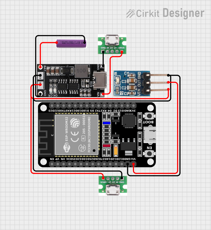
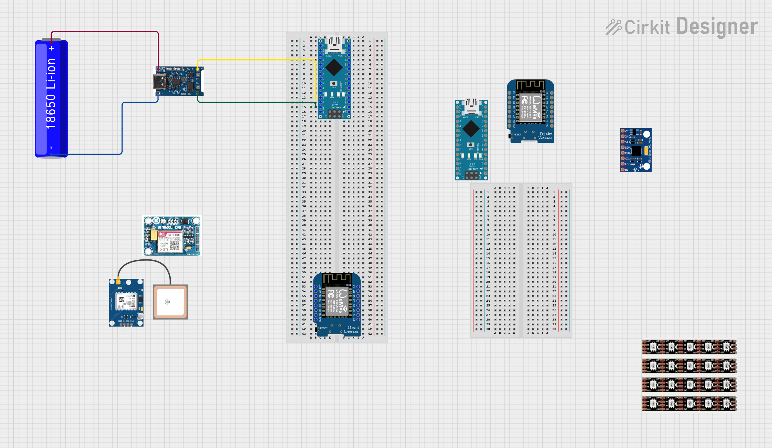
  1. Connect the Battery:

    • Connect the positive terminal of the LiPo battery to the BAT pin.
    • Connect the negative terminal of the LiPo battery to the GND pin.
  2. Power Supply:

    • Plug a Micro-USB cable into the USB port and connect it to a USB power source.
  3. Charging Process:

    • The red LED will illuminate to indicate that the battery is charging.
    • Once the battery reaches 4.2V, the charging will stop, and the green LED will light up, indicating that the charge is complete.

Important Considerations and Best Practices

  • Battery Protection: Ensure that the LiPo battery has a built-in protection circuit to prevent over-discharge and short-circuiting.
  • Monitoring: Never leave the battery unattended while charging.
  • Heat Management: Make sure the charging area is well-ventilated as LiPo batteries can generate heat during charging.
  • Cable Quality: Use a high-quality Micro-USB cable to ensure a stable power supply.

Troubleshooting and FAQs

Common Issues

  • Red LED Not Lighting Up:

    • Check the Micro-USB cable and power source.
    • Ensure the battery is properly connected to the BAT and GND pins.
  • Green LED Not Lighting Up After Charging:

    • Verify that the battery is not already fully charged.
    • Check if the battery voltage is below the charge cutoff voltage.

Solutions and Tips for Troubleshooting

  • Ensure Proper Connections: Double-check all connections to the charger and battery.
  • Power Source: Try a different USB power source to rule out power issues.
  • Battery Health: Inspect the LiPo battery for any signs of damage or swelling.

FAQs

  • Q: Can I charge multiple batteries at once?

    • A: No, this charger is designed for single-cell LiPo batteries only.
  • Q: What should I do if the battery gets hot during charging?

    • A: Stop charging immediately and disconnect the battery. Allow it to cool down before inspecting for damage.
  • Q: Can I adjust the charge current?

    • A: The default charge current is 500mA. To change it, you would need to modify the onboard resistor, which is not recommended without proper knowledge of electronics.

Example Code for Arduino UNO

This section provides an example of how to monitor the charging status using an Arduino UNO.

// Define the charge status pins
const int CHARGE_PIN = 2; // Connect to the charging indicator LED
const int FULL_PIN = 3;   // Connect to the full charge indicator LED

void setup() {
  pinMode(CHARGE_PIN, INPUT);
  pinMode(FULL_PIN, INPUT);
  Serial.begin(9600);
}

void loop() {
  // Read the charging status
  bool isCharging = digitalRead(CHARGE_PIN);
  bool isFull = digitalRead(FULL_PIN);

  // Output the status to the Serial Monitor
  if (isCharging) {
    Serial.println("Battery is charging...");
  } else if (isFull) {
    Serial.println("Charge complete!");
  } else {
    Serial.println("Battery is not charging.");
  }

  // Wait for a second before reading again
  delay(1000);
}

Note: The above code assumes that the charging and full charge indicator LEDs are connected to digital pins 2 and 3 of the Arduino UNO, respectively. Adjust the pin numbers as needed for your setup.