
How to Use SS-12D03 Miniature SPDT Slide Switch: Examples, Pinouts, and Specs
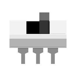
 Design with SS-12D03 Miniature SPDT Slide Switch in Cirkit Designer
Introduction
The SS-12D03 Miniature SPDT Slide Switch is a compact, single-pole double-throw (SPDT) switch designed for controlling electrical circuits. It features a sliding lever mechanism that allows users to toggle between two electrical paths. This versatile switch is widely used in low-power electronic applications due to its small size, reliability, and ease of use.
Explore Projects Built with SS-12D03 Miniature SPDT Slide Switch
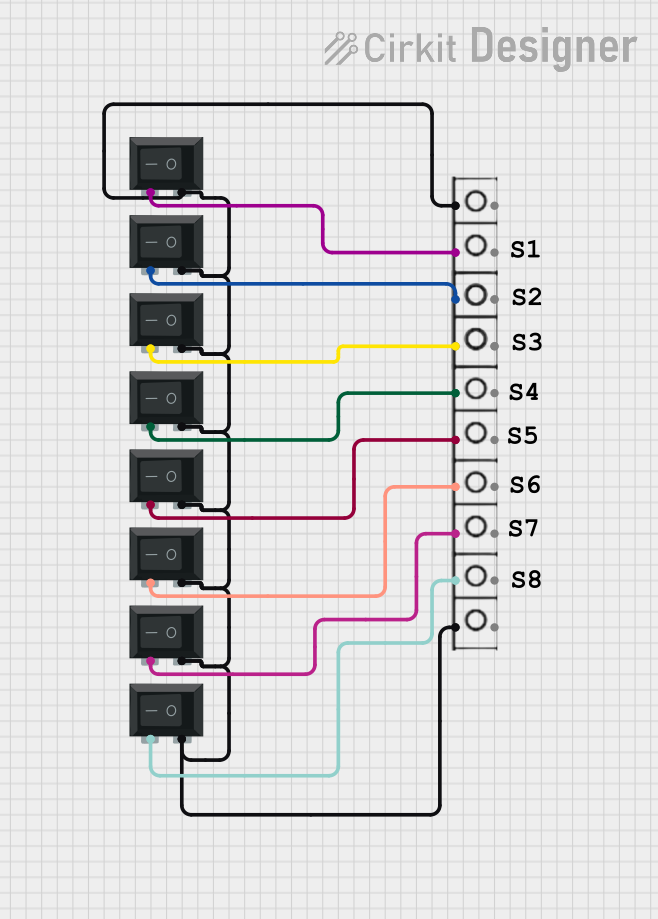 Open Project in Cirkit Designer
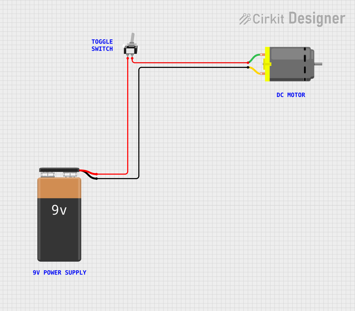 Open Project in Cirkit Designer
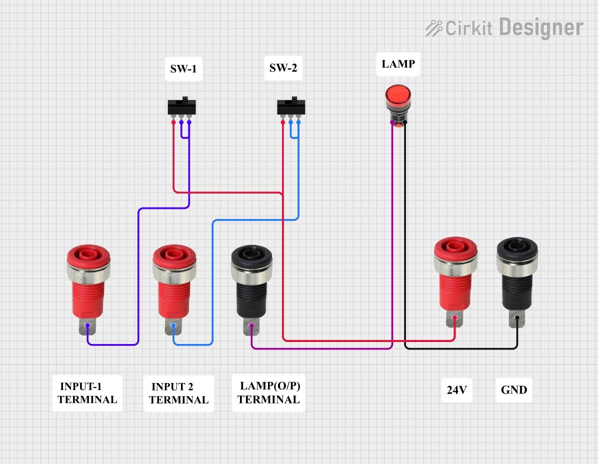 Open Project in Cirkit Designer
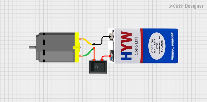 Open Project in Cirkit Designer
Explore Projects Built with SS-12D03 Miniature SPDT Slide Switch
Open Project in Cirkit DesignerOpen Project in Cirkit DesignerOpen Project in Cirkit DesignerOpen Project in Cirkit DesignerCommon Applications and Use Cases
- Power control in small electronic devices
- Mode selection in circuits (e.g., switching between operational modes)
- Signal routing in audio, communication, or control systems
- DIY electronics and prototyping projects
- Embedded systems and Arduino-based projects
Technical Specifications
Below are the key technical details for the SS-12D03 slide switch:
| Parameter | Specification |
|---|---|
| Manufacturer | Generic / Manufacturer not specified |
| Part Number | SS-12D03 1P2T, 3-Pin Slide Switch |
| Switch Type | SPDT (Single Pole Double Throw) |
| Number of Pins | 3 |
| Rated Voltage | 12V DC |
| Rated Current | 0.5A (500mA) |
| Contact Resistance | ≤ 30 mΩ |
| Insulation Resistance | ≥ 100 MΩ |
| Operating Temperature | -20°C to +70°C |
| Mechanical Life | 10,000 cycles |
| Dimensions | 12mm x 5mm x 3.5mm |
| Mounting Type | Through-hole (THT) |
Pin Configuration and Descriptions
The SS-12D03 has three pins, which are configured as follows:
| Pin Number | Name | Description |
|---|---|---|
| 1 | Common (C) | The central pin that connects to either Pin 2 or Pin 3 depending on the lever's position. |
| 2 | Normally Open (NO) | Connected to the Common pin when the switch lever is in Position 1. |
| 3 | Normally Closed (NC) | Connected to the Common pin when the switch lever is in Position 2. |
Usage Instructions
How to Use the SS-12D03 in a Circuit
- Identify the Pins: Locate the three pins on the switch. The middle pin is the Common (C), while the two outer pins are Normally Open (NO) and Normally Closed (NC).
- Connect the Circuit:
- Connect the Common pin to the input signal or power source.
- Connect the Normally Open pin to the first output or circuit path.
- Connect the Normally Closed pin to the second output or circuit path.
- Toggle the Switch: Slide the lever to switch between the two output paths. The lever's position determines whether the Common pin is connected to the NO or NC pin.
Important Considerations and Best Practices
- Voltage and Current Ratings: Ensure the switch is used within its rated voltage (12V DC) and current (0.5A) to avoid damage.
- Soldering: When soldering the switch to a PCB, use a low-temperature soldering iron to prevent overheating the plastic housing.
- Mechanical Stress: Avoid applying excessive force to the lever to maintain the switch's mechanical integrity.
- Debouncing: If the switch is used in digital circuits, consider implementing software or hardware debouncing to eliminate signal noise caused by rapid contact changes.
Example: Using the SS-12D03 with an Arduino UNO
The SS-12D03 can be used to toggle between two LEDs using an Arduino UNO. Below is an example circuit and code:
Circuit Connections
- Connect the Common pin of the switch to Arduino pin 2.
- Connect the Normally Open pin to a 10kΩ pull-down resistor and Arduino pin 3.
- Connect the Normally Closed pin to a 10kΩ pull-down resistor and Arduino pin 4.
- Connect two LEDs to Arduino pins 8 and 9 with appropriate current-limiting resistors.
Arduino Code
// Define pin connections for the switch and LEDs
const int switchCommon = 2;  // Common pin of the switch
const int switchNO = 3;      // Normally Open pin
const int switchNC = 4;      // Normally Closed pin
const int led1 = 8;          // LED connected to Normally Open path
const int led2 = 9;          // LED connected to Normally Closed path

void setup() {
  // Set up switch pins as inputs
  pinMode(switchCommon, INPUT);
  pinMode(switchNO, INPUT);
  pinMode(switchNC, INPUT);

  // Set up LED pins as outputs
  pinMode(led1, OUTPUT);
  pinMode(led2, OUTPUT);
}

void loop() {
  // Read the state of the switch
  int noState = digitalRead(switchNO);  // State of Normally Open pin
  int ncState = digitalRead(switchNC); // State of Normally Closed pin

  // Control LEDs based on switch position
  if (noState == HIGH) {
    digitalWrite(led1, HIGH);  // Turn on LED1
    digitalWrite(led2, LOW);   // Turn off LED2
  } else if (ncState == HIGH) {
    digitalWrite(led1, LOW);   // Turn off LED1
    digitalWrite(led2, HIGH);  // Turn on LED2
  }
}
Troubleshooting and FAQs
Common Issues
Switch Not Functioning Properly:
- Cause: Poor soldering or loose connections.
- Solution: Recheck solder joints and ensure all connections are secure.
Intermittent Behavior:
- Cause: Contact wear or dirt inside the switch.
- Solution: Clean the switch contacts with isopropyl alcohol or replace the switch if worn out.
LEDs Not Responding in Arduino Circuit:
- Cause: Incorrect pin connections or code errors.
- Solution: Verify the wiring and ensure the Arduino code matches the circuit setup.
FAQs
Q: Can the SS-12D03 handle AC voltage?
A: No, the SS-12D03 is designed for low-voltage DC applications only. Using it with AC voltage may damage the switch or cause unsafe operation.
Q: How do I debounce the switch in software?
A: You can use a delay or a state-change detection algorithm in your code to filter out rapid signal changes caused by mechanical bouncing.
Q: Is the SS-12D03 suitable for high-power applications?
A: No, this switch is rated for a maximum of 12V DC and 0.5A. For high-power applications, consider using a relay or a switch with higher ratings.