How to Use pid : Examples, Pinouts, and Specs
Introduction
The TC513 PID Controller, manufactured by :select, is a versatile and widely used control loop feedback mechanism. It is designed to continuously calculate an error value as the difference between a desired setpoint and a measured process variable. The controller then applies a correction based on proportional, integral, and derivative terms to minimize the error. This makes the TC513 ideal for applications requiring precise control, such as temperature regulation, motor speed control, and process automation.
Explore Projects Built with pid

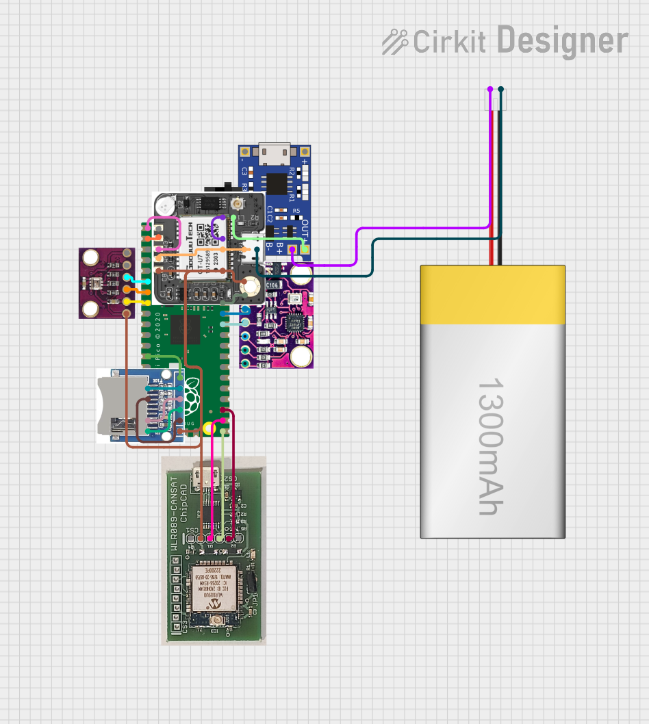
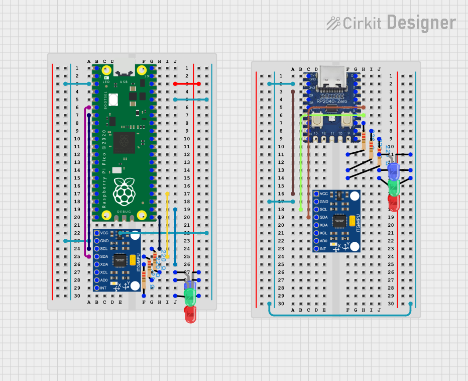

Explore Projects Built with pid
Technical Specifications
Key Technical Details
| Parameter | Value |
|---|---|
| Manufacturer | :select |
| Part ID | TC513 |
| Supply Voltage | 5V DC |
| Operating Current | 10 mA |
| Output Type | Analog |
| Proportional Range | 0-100% |
| Integral Time | 0-10 seconds |
| Derivative Time | 0-10 seconds |
| Operating Temperature Range | -40°C to 85°C |
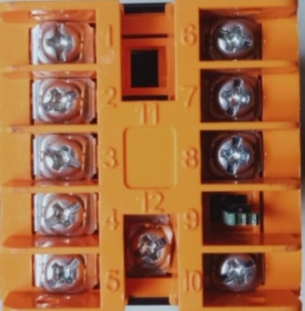
Pin Configuration and Descriptions
| Pin Number | Pin Name | Description |
|---|---|---|
| 1 | VCC | Power supply (5V DC) |
| 2 | GND | Ground |
| 3 | IN | Input signal (process variable) |
| 4 | OUT | Output signal (control variable) |
| 5 | SET | Setpoint input (desired value) |
| 6 | P | Proportional gain adjustment |
| 7 | I | Integral gain adjustment |
| 8 | D | Derivative gain adjustment |
Usage Instructions
How to Use the TC513 in a Circuit
- Power Supply: Connect the VCC pin to a 5V DC power supply and the GND pin to the ground.
- Input Signal: Connect the IN pin to the process variable signal that you want to control.
- Output Signal: Connect the OUT pin to the actuator or device that will be controlled by the PID controller.
- Setpoint Input: Connect the SET pin to the desired setpoint value.
- Gain Adjustments: Use the P, I, and D pins to adjust the proportional, integral, and derivative gains respectively.
Important Considerations and Best Practices
- Stability: Ensure that the PID gains are tuned properly to avoid oscillations and ensure system stability.
- Noise Filtering: Use appropriate filtering techniques to minimize noise in the input signal.
- Temperature: Operate the TC513 within the specified temperature range to ensure reliable performance.
- Power Supply: Use a stable and regulated 5V DC power supply to avoid fluctuations in the control signal.
Troubleshooting and FAQs
Common Issues and Solutions
Oscillations in Output:
- Cause: Improper tuning of PID gains.
- Solution: Adjust the proportional, integral, and derivative gains to achieve stable control.
No Output Signal:
- Cause: Incorrect wiring or insufficient power supply.
- Solution: Verify the wiring connections and ensure a stable 5V DC power supply.
Slow Response:
- Cause: Low proportional gain or high integral time.
- Solution: Increase the proportional gain or decrease the integral time to improve response time.
FAQs
Q1: How do I tune the PID gains? A1: Start with a low proportional gain and gradually increase it until you observe oscillations. Then, adjust the integral and derivative gains to minimize the oscillations and achieve stable control.
Q2: Can I use the TC513 with an Arduino UNO? A2: Yes, the TC513 can be interfaced with an Arduino UNO. Below is an example code to demonstrate the usage:
// Example code to interface TC513 PID Controller with Arduino UNO

const int setPointPin = A0; // Setpoint input pin
const int processVarPin = A1; // Process variable input pin
const int controlVarPin = 9; // Control variable output pin

void setup() {
  pinMode(setPointPin, INPUT);
  pinMode(processVarPin, INPUT);
  pinMode(controlVarPin, OUTPUT);
  Serial.begin(9600);
}

void loop() {
  int setPoint = analogRead(setPointPin); // Read setpoint value
  int processVar = analogRead(processVarPin); // Read process variable
  int controlVar = calculatePID(setPoint, processVar); // Calculate PID output
  analogWrite(controlVarPin, controlVar); // Output control variable
  delay(100); // Delay for stability
}

int calculatePID(int setPoint, int processVar) {
  // Placeholder function for PID calculation
  // Implement your PID algorithm here
  int error = setPoint - processVar;
  int controlVar = error; // Simple proportional control for demonstration
  return controlVar;
}
This code reads the setpoint and process variable values, calculates the PID output, and writes the control variable to the output pin. You can implement your PID algorithm in the calculatePID function.
By following this documentation, users can effectively utilize the TC513 PID Controller in their projects, ensuring precise and stable control of various processes.