How to Use eps32_wemos: Examples, Pinouts, and Specs
Introduction
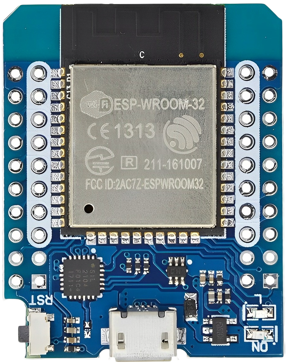
The ESP32 Wemos development board is a versatile and powerful platform designed for a wide range of Internet of Things (IoT) applications. It features the ESP32 module, which is a dual-core processor with integrated Wi-Fi and Bluetooth capabilities. The board includes a USB connection for programming and serial communication, a battery charging circuit for mobile applications, and various pins and headers for connecting sensors, actuators, and other peripherals.
Explore Projects Built with eps32_wemos


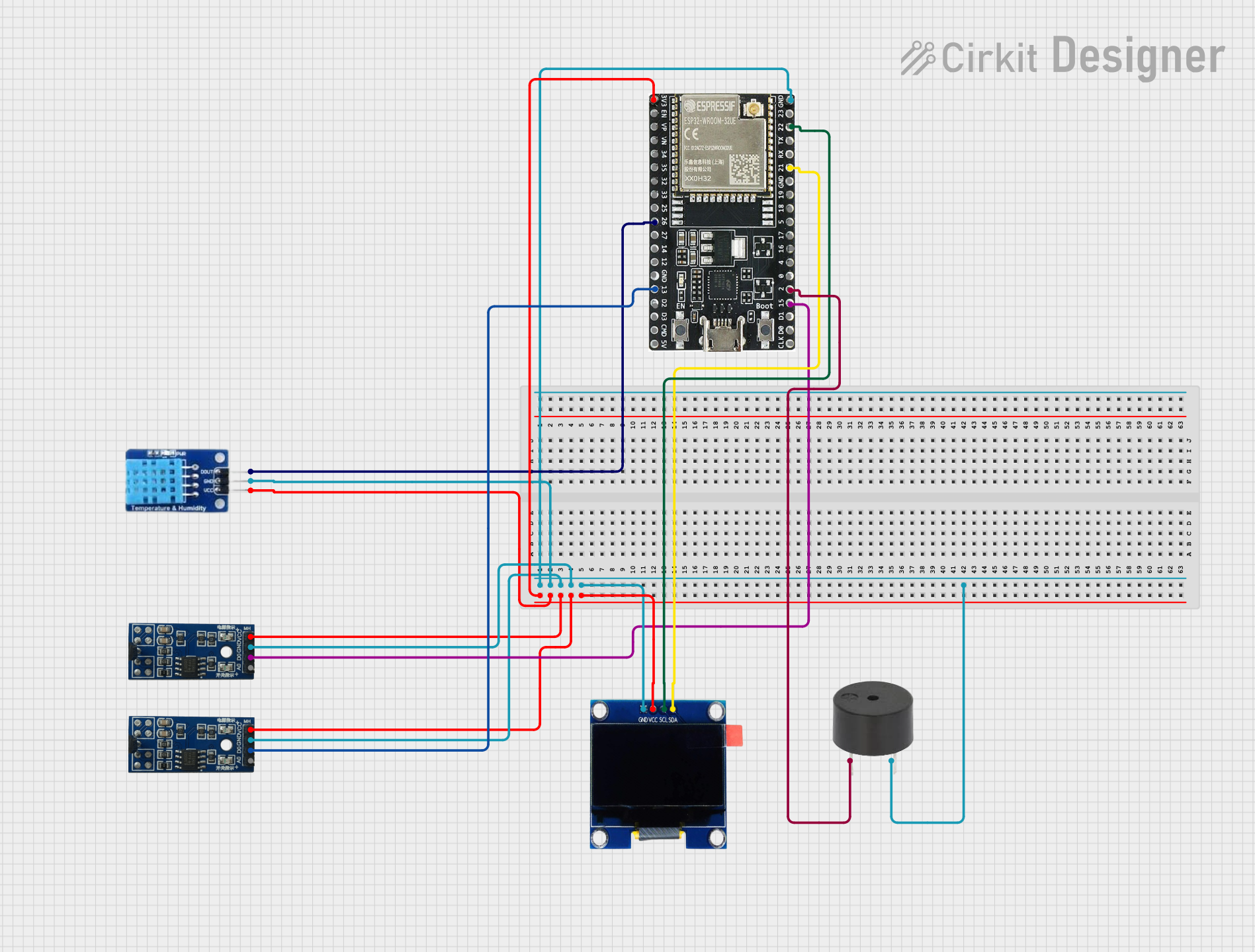
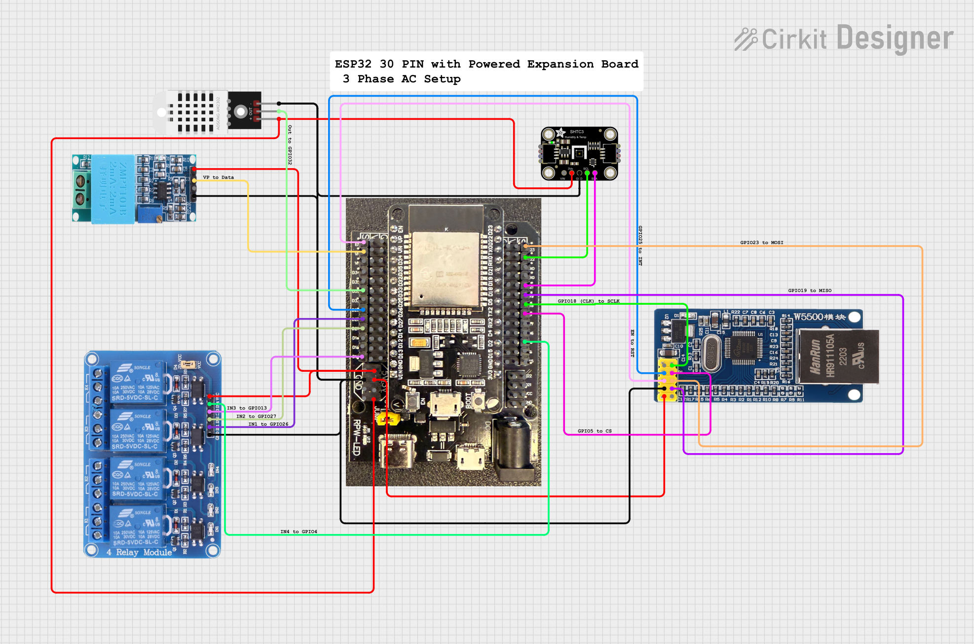
Explore Projects Built with eps32_wemos
Common Applications and Use Cases
- Smart home devices
- Wireless sensor networks
- IoT applications
- Wearable electronics
- DIY projects and prototyping
Technical Specifications
Key Technical Details
- Microcontroller: ESP32
- Operating Voltage: 3.3V
- Input Voltage (recommended): 5V via USB or battery
- Digital I/O Pins: 22
- Analog Input Pins: 6 (ADC channels)
- Flash Memory: 4MB
- SRAM: 520 KB
- Clock Speed: 240 MHz
- Wi-Fi: 802.11 b/g/n
- Bluetooth: v4.2 BR/EDR and BLE
- USB-to-UART Bridge: CP2102
Pin Configuration and Descriptions
| Pin Number | Function | Description |
|---|---|---|
| 1 | 3V3 | 3.3V power supply |
| 2 | GND | Ground |
| 3 | EN | Reset pin (active low) |
| 4 | VP | GPIO36, ADC1_0, Sensor VP |
| 5 | VN | GPIO39, ADC1_3, Sensor VN |
| 6 | D34 | GPIO34, ADC1_6, Input only |
| 7 | D35 | GPIO35, ADC1_7, Input only |
| 8 | D32 | GPIO32, ADC1_4, XTAL_32K |
| 9 | D33 | GPIO33, ADC1_5, XTAL_32K |
| 10 | D25 | GPIO25, ADC2_8, DAC_1 |
| ... | ... | ... |
| n | TXD0 | GPIO1, U0TXD, UART0 Transmit |
| n+1 | RXD0 | GPIO3, U0RXD, UART0 Receive |
| n+2 | SDA | GPIO21, I2C SDA |
| n+3 | SCL | GPIO22, I2C SCL |
| n+4 | 5V | 5V power supply via USB or battery |
| n+5 | GND | Ground |
Note: This is a partial list of pins for illustration purposes. Please refer to the official pinout diagram for complete details.
Usage Instructions
How to Use the Component in a Circuit
Powering the Board:
- Connect the USB cable to the board and a computer or USB power source.
- Alternatively, connect a battery to the designated battery connector.
Programming the Board:
- Install the necessary drivers for the USB-to-UART bridge (CP2102).
- Use the Arduino IDE or other development environments to write and upload your code.
Connecting Peripherals:
- Use the digital and analog pins to connect sensors and actuators.
- Ensure that the peripherals are compatible with the board's operating voltage (3.3V).
Important Considerations and Best Practices
- Always disconnect the board from power sources before making or altering connections.
- Use a logic level converter if you need to interface with 5V components.
- Avoid drawing more current than the board's maximum rating to prevent damage.
- Use external power sources when connecting power-hungry peripherals.
Troubleshooting and FAQs
Common Issues Users Might Face
- Board not recognized by the computer:
- Ensure the USB cable is properly connected and the drivers are installed.
- Unable to upload code:
- Check the selected board and port in your development environment.
- Press the boot button on the board when initiating the upload process.
- Peripherals not working:
- Verify the connections and ensure that the peripherals are powered correctly.
Solutions and Tips for Troubleshooting
- Restart the development environment and reconnect the board.
- Use a multimeter to check for proper voltage levels at the board's pins.
- Consult the ESP32 Wemos community forums for support and advice.
Example Code for Arduino UNO
// Blink an LED connected to pin 2 on the ESP32 Wemos board
#define LED_PIN 2

void setup() {
  pinMode(LED_PIN, OUTPUT); // Initialize the LED pin as an output
}

void loop() {
  digitalWrite(LED_PIN, HIGH); // Turn the LED on
  delay(1000);                // Wait for a second
  digitalWrite(LED_PIN, LOW);  // Turn the LED off
  delay(1000);                // Wait for a second
}
Note: The above code is a simple example to get started. For more complex applications, refer to the ESP32 Wemos documentation and libraries.
Remember to always check the official documentation for the most up-to-date information on the ESP32 Wemos development board.