
How to Use ESP32-S3 1.75inch AMOLED Round : Examples, Pinouts, and Specs
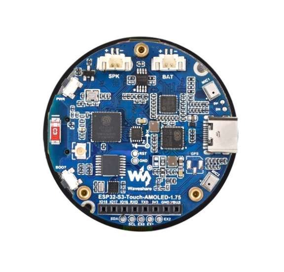
 Design with ESP32-S3 1.75inch AMOLED Round in Cirkit Designer
Introduction
The ESP32-S3 1.75inch AMOLED Round by WaveShare is a compact display module that combines a high-resolution 1.75-inch AMOLED screen with the powerful ESP32-S3 microcontroller. This module is designed for applications requiring vibrant graphics, low power consumption, and wireless connectivity. The ESP32-S3 provides dual-core processing, Wi-Fi, and Bluetooth capabilities, making it ideal for IoT, wearable devices, smart home systems, and portable displays.
Explore Projects Built with ESP32-S3 1.75inch AMOLED Round
 Open Project in Cirkit Designer
 Open Project in Cirkit Designer
 Open Project in Cirkit Designer
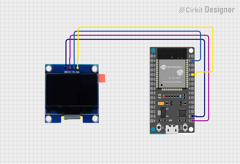 Open Project in Cirkit Designer
Explore Projects Built with ESP32-S3 1.75inch AMOLED Round
Open Project in Cirkit DesignerOpen Project in Cirkit DesignerOpen Project in Cirkit DesignerOpen Project in Cirkit DesignerCommon Applications
- Smartwatches and wearable devices
- IoT dashboards and control panels
- Portable media players
- Smart home automation interfaces
- Educational and prototyping projects
Technical Specifications
Key Technical Details
| Parameter | Specification |
|---|---|
| Display Type | 1.75-inch AMOLED, round |
| Resolution | 480 x 480 pixels |
| Color Depth | 16.7M colors |
| Microcontroller | ESP32-S3 |
| Wireless Connectivity | Wi-Fi 802.11 b/g/n, Bluetooth 5.0 |
| Operating Voltage | 3.3V |
| Power Consumption | Low power consumption |
| Interface | SPI |
| Touch Panel | Capacitive (optional, depending on model) |
| Dimensions | 44mm diameter |
Pin Configuration and Descriptions
The module features a standard pin header for easy integration. Below is the pinout:
| Pin Name | Type | Description |
|---|---|---|
| VCC | Power | Power input (3.3V) |
| GND | Ground | Ground connection |
| SCK | Input | SPI clock signal |
| MOSI | Input | SPI master-out, slave-in |
| MISO | Output | SPI master-in, slave-out |
| CS | Input | Chip select for SPI |
| DC | Input | Data/Command control |
| RST | Input | Reset signal |
| BL | Input | Backlight control (PWM supported) |
| TP_INT | Output | Touch panel interrupt (if touch-enabled) |
Usage Instructions
How to Use the Component in a Circuit
- Power Supply: Connect the VCC pin to a 3.3V power source and GND to ground.
- SPI Communication: Connect the SPI pins (SCK, MOSI, MISO, CS) to the corresponding SPI pins on your microcontroller or development board.
- Control Signals: Use the DC pin to toggle between data and command modes. The RST pin can be used to reset the display.
- Backlight Control: The BL pin can be connected to a PWM-capable pin on your microcontroller to adjust the screen brightness.
- Touch Panel (Optional): If your module includes a touch panel, connect the TP_INT pin to an interrupt-capable pin on your microcontroller.
Important Considerations and Best Practices
- Ensure the power supply is stable and within the specified voltage range (3.3V).
- Use appropriate pull-up or pull-down resistors for SPI lines if required.
- Avoid prolonged exposure to static electricity to prevent damage to the AMOLED screen.
- If using the touch panel, debounce the interrupt signal in software to avoid false triggers.
Example Code for Arduino UNO
Below is an example of how to interface the ESP32-S3 1.75inch AMOLED Round with an Arduino UNO using the SPI interface. Note that the ESP32-S3 is the onboard microcontroller, but this example demonstrates external control.
#include <SPI.h>

// Define SPI pins
#define CS_PIN 10    // Chip select pin
#define DC_PIN 9     // Data/Command pin
#define RST_PIN 8    // Reset pin
#define BL_PIN 6     // Backlight control pin (PWM)

// Function to initialize the display
void initDisplay() {
  pinMode(CS_PIN, OUTPUT);
  pinMode(DC_PIN, OUTPUT);
  pinMode(RST_PIN, OUTPUT);
  pinMode(BL_PIN, OUTPUT);

  // Reset the display
  digitalWrite(RST_PIN, LOW);
  delay(100);
  digitalWrite(RST_PIN, HIGH);
  delay(100);

  // Initialize SPI
  SPI.begin();
  digitalWrite(CS_PIN, HIGH); // Deselect the display
}

// Function to send a command to the display
void sendCommand(uint8_t cmd) {
  digitalWrite(CS_PIN, LOW);  // Select the display
  digitalWrite(DC_PIN, LOW);  // Command mode
  SPI.transfer(cmd);
  digitalWrite(CS_PIN, HIGH); // Deselect the display
}

// Function to send data to the display
void sendData(uint8_t data) {
  digitalWrite(CS_PIN, LOW);  // Select the display
  digitalWrite(DC_PIN, HIGH); // Data mode
  SPI.transfer(data);
  digitalWrite(CS_PIN, HIGH); // Deselect the display
}

void setup() {
  initDisplay();
  analogWrite(BL_PIN, 128); // Set backlight brightness (50%)

  // Example: Clear the screen with a command
  sendCommand(0x01); // Clear display command (example)
}

void loop() {
  // Add your display logic here
}
Troubleshooting and FAQs
Common Issues
Display Not Turning On
- Ensure the VCC and GND connections are secure and the power supply is 3.3V.
- Check the RST pin; ensure it is not held low.
No Response from the Display
- Verify the SPI connections and ensure the correct pins are used.
- Check the CS, DC, and RST signals for proper operation.
Touch Panel Not Responding
- Ensure the TP_INT pin is connected to an interrupt-capable pin on your microcontroller.
- Verify that the touch panel is enabled in your software.
Flickering or Dim Display
- Check the BL pin connection and ensure the PWM signal is stable.
- Verify that the power supply can provide sufficient current.
Solutions and Tips
- Use a logic analyzer or oscilloscope to debug SPI communication if the display is unresponsive.
- Refer to the WaveShare datasheet for detailed initialization sequences and commands.
- If using the ESP32-S3 onboard microcontroller, leverage its built-in libraries for SPI and display control to simplify development.