Cirkit Designer Logo
Cirkit Designer
Your all-in-one circuit design IDE
Home / 
Component Documentation

How to Use Solid State Relay 1x: Examples, Pinouts, and Specs

Image of Solid State Relay 1x
Cirkit Designer LogoDesign with Solid State Relay 1x in Cirkit Designer

Introduction

A Solid State Relay (SSR) is an electronic component that switches electrical circuits on or off using semiconductor devices. Unlike mechanical relays, SSRs have no moving parts, which allows for faster switching, reduced noise, and increased lifespan. They are ideal for applications requiring precise control, such as in industrial automation, temperature control, and lighting systems.

Explore Projects Built with Solid State Relay 1x

Use Cirkit Designer to design, explore, and prototype these projects online. Some projects support real-time simulation. Click "Open Project" to start designing instantly!
ESP8266 NodeMCU Controlled SSR for Smart Power Management
Image of Copy of SISTEMA DE CONTROL POR DEMANDA DE DIOXIDO DE CARBONO: A project utilizing Solid State Relay 1x in a practical application
This circuit features an ESP8266 NodeMCU microcontroller that controls a solid-state relay to switch a 120V fan and a red lamp on and off. A green LED is used as an indicator for the relay's operation, and the circuit is powered by a 220V AC power source connected through an IEC320 inlet.
Cirkit Designer LogoOpen Project in Cirkit Designer
ESP32 Smart Socket with Energy Monitoring and OLED Display
Image of Energy Meter: A project utilizing Solid State Relay 1x in a practical application
This circuit is a smart socket for energy monitoring, utilizing an ESP32 microcontroller to read voltage and current from ZMPT101B and ACS712 sensors. The readings are displayed on a 0.96" OLED screen, and a relay module is used to control a connected load, such as a bulb, remotely. The system is powered by a 220V AC source, converted to DC by an HLK-PM01 module.
Cirkit Designer LogoOpen Project in Cirkit Designer
PID Temperature Control System with Thermocouple and SSR
Image of IR: A project utilizing Solid State Relay 1x in a practical application
This circuit is a temperature control system that uses a thermocouple to measure temperature and a PID controller to regulate it. The PID controller drives a solid-state relay (SSR) to control an external load, with power supplied through an AC inlet socket.
Cirkit Designer LogoOpen Project in Cirkit Designer
Battery-Powered IR Sensor Controlled Relay Module
Image of New: A project utilizing Solid State Relay 1x in a practical application
This circuit uses an IR sensor to control a 1 Channel 5V Relay Module, which is powered by a 9V battery. The IR sensor detects an object and sends a signal to the relay module to switch its state, enabling or disabling the connected load.
Cirkit Designer LogoOpen Project in Cirkit Designer

Explore Projects Built with Solid State Relay 1x

Use Cirkit Designer to design, explore, and prototype these projects online. Some projects support real-time simulation. Click "Open Project" to start designing instantly!
Image of Copy of SISTEMA DE CONTROL POR DEMANDA DE DIOXIDO DE CARBONO: A project utilizing Solid State Relay 1x in a practical application
ESP8266 NodeMCU Controlled SSR for Smart Power Management
This circuit features an ESP8266 NodeMCU microcontroller that controls a solid-state relay to switch a 120V fan and a red lamp on and off. A green LED is used as an indicator for the relay's operation, and the circuit is powered by a 220V AC power source connected through an IEC320 inlet.
Cirkit Designer LogoOpen Project in Cirkit Designer
Image of Energy Meter: A project utilizing Solid State Relay 1x in a practical application
ESP32 Smart Socket with Energy Monitoring and OLED Display
This circuit is a smart socket for energy monitoring, utilizing an ESP32 microcontroller to read voltage and current from ZMPT101B and ACS712 sensors. The readings are displayed on a 0.96" OLED screen, and a relay module is used to control a connected load, such as a bulb, remotely. The system is powered by a 220V AC source, converted to DC by an HLK-PM01 module.
Cirkit Designer LogoOpen Project in Cirkit Designer
Image of IR: A project utilizing Solid State Relay 1x in a practical application
PID Temperature Control System with Thermocouple and SSR
This circuit is a temperature control system that uses a thermocouple to measure temperature and a PID controller to regulate it. The PID controller drives a solid-state relay (SSR) to control an external load, with power supplied through an AC inlet socket.
Cirkit Designer LogoOpen Project in Cirkit Designer
Image of New: A project utilizing Solid State Relay 1x in a practical application
Battery-Powered IR Sensor Controlled Relay Module
This circuit uses an IR sensor to control a 1 Channel 5V Relay Module, which is powered by a 9V battery. The IR sensor detects an object and sends a signal to the relay module to switch its state, enabling or disabling the connected load.
Cirkit Designer LogoOpen Project in Cirkit Designer

Technical Specifications

General Features

  • Switching Type: AC or DC (depending on model)
  • Control Voltage Range: Typically 3-32V DC
  • Load Voltage Range: Typically 24-380V AC or similar range for DC models
  • Load Current Rating: Commonly up to 25A (varies by model)
  • Isolation Voltage: Typically >2000V
  • Switching Speed: Instantaneous (milliseconds or less)
  • Operating Temperature: -30°C to +75°C (varies by model)

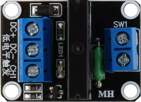
Pin Configuration and Descriptions

Pin Number Description Notes
1 Control Voltage (+) Input from control circuit
2 Control Voltage (-) Input from control circuit
3 Load Voltage (Line) Connect to the load circuit
4 Load Voltage (Neutral/Return) Connect to the load circuit

Note: Pin numbers are for reference and may vary by manufacturer. Always consult the datasheet for exact pinout information.
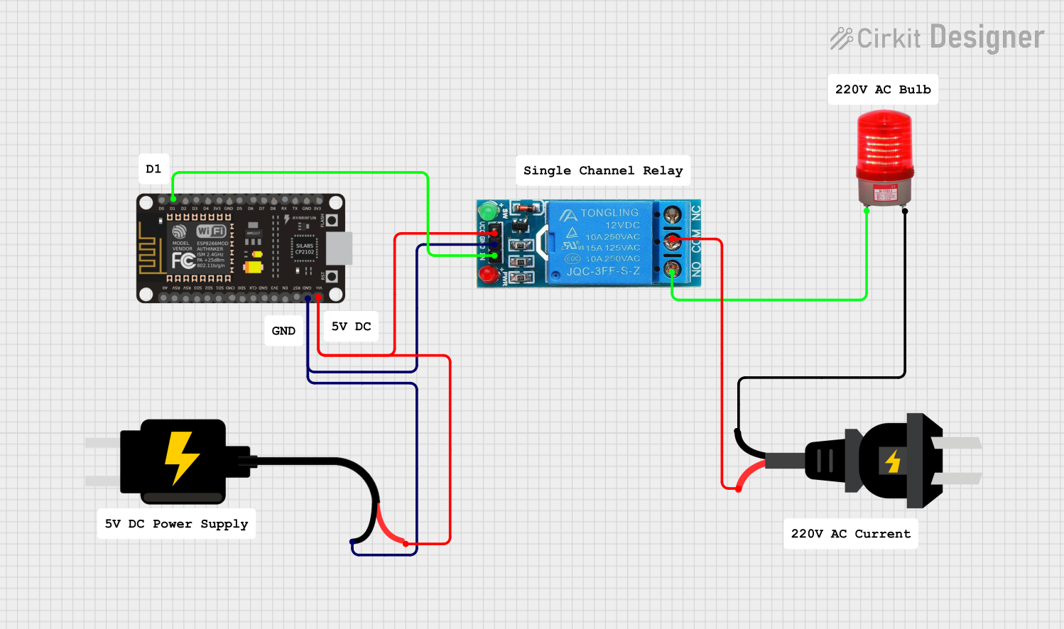
Usage Instructions

Connecting to a Circuit

  1. Control Circuit Connection:

    • Connect the positive control voltage to Pin 1.
    • Connect the negative control voltage to Pin 2.
  2. Load Circuit Connection:

    • Connect the line voltage of the load to Pin 3.
    • Connect the neutral or return line of the load to Pin 4.

Best Practices

  • Use a heat sink if the SSR is expected to handle loads near its maximum current rating.
  • Ensure proper isolation between the control and load circuits.
  • Use a snubber circuit across the load if inductive loads are switched to prevent voltage spikes.
  • Always verify the SSR's load voltage and current ratings match the requirements of your application.

Example Code for Arduino UNO

The following example demonstrates how to control an SSR with an Arduino UNO:

// Define the SSR control pin
const int ssrPin = 7;

void setup() {
  // Set the SSR pin as an output
  pinMode(ssrPin, OUTPUT);
}

void loop() {
  // Turn on the SSR (activate the connected load)
  digitalWrite(ssrPin, HIGH);
  delay(1000); // Keep the load on for 1 second
  
  // Turn off the SSR (deactivate the connected load)
  digitalWrite(ssrPin, LOW);
  delay(1000); // Keep the load off for 1 second
}

Note: The control voltage for the SSR must be compatible with the Arduino output voltage (5V).

Troubleshooting and FAQs

Common Issues

  • SSR does not switch on: Check the control voltage and connections.
  • Load does not power on: Verify load connections and ensure the SSR's ratings match the load.
  • SSR overheats: Ensure proper heat sinking and current ratings are not exceeded.

FAQs

Q: Can I use an SSR for both AC and DC loads? A: SSRs are typically designed for either AC or DC loads. Make sure to select the appropriate type for your application.

Q: How do I know if my SSR is functioning properly? A: Measure the control voltage across the SSR's input. When activated, the output should allow current to pass through to the load.

Q: Is it necessary to use a heat sink with an SSR? A: For high-current applications or prolonged use, a heat sink is recommended to dissipate heat and ensure longevity.

Q: Can I control an SSR with a microcontroller like an Arduino? A: Yes, as long as the control voltage is within the microcontroller's output range and the SSR's input range.

For further assistance, consult the manufacturer's datasheet and technical support resources.