How to Use push button: Examples, Pinouts, and Specs
Introduction
A push button is a momentary switch that completes a circuit when pressed and breaks the circuit when released. It is a simple yet essential component in electronics, commonly used for user input in devices such as calculators, remote controls, and microcontroller-based projects. Push buttons are available in various shapes and sizes, making them versatile for different applications.
Explore Projects Built with push button


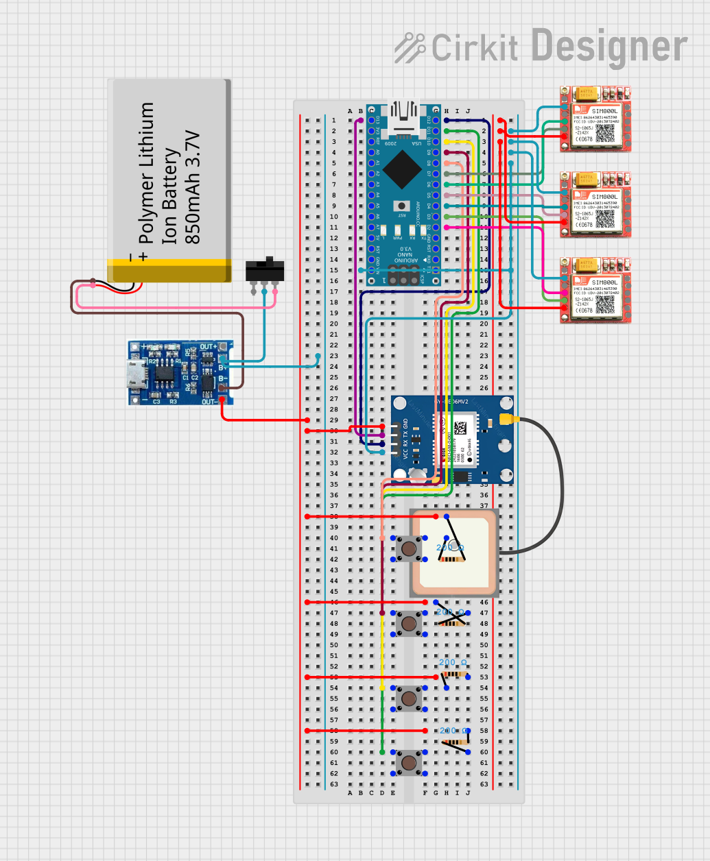
Explore Projects Built with push button
Common Applications and Use Cases
- User input for microcontroller projects (e.g., Arduino, Raspberry Pi)
- Reset or power buttons in electronic devices
- Control switches in industrial equipment
- Doorbells and alarm systems
- Game controllers and interactive devices
Technical Specifications
Below are the general technical specifications for a standard push button:
| Parameter | Value |
|---|---|
| Operating Voltage | 3.3V to 12V (typical) |
| Maximum Current Rating | 50mA to 500mA (depending on type) |
| Contact Resistance | ≤ 100 mΩ |
| Insulation Resistance | ≥ 100 MΩ |
| Operating Temperature | -20°C to +70°C |
| Mechanical Lifespan | 100,000 to 1,000,000 presses |
Pin Configuration and Descriptions
Push buttons typically have four pins, but only two are electrically connected at any given time. The pin configuration is as follows:
| Pin Number | Description |
|---|---|
| Pin 1 | Connected to one side of the switch |
| Pin 2 | Connected to the other side of the switch |
| Pin 3 | Internally connected to Pin 1 |
| Pin 4 | Internally connected to Pin 2 |
Note: Pins 1 and 3 are internally connected, as are Pins 2 and 4. This allows for flexibility in wiring.
Usage Instructions
How to Use the Push Button in a Circuit
- Identify the Pins: Use a multimeter to confirm which pins are internally connected (Pins 1 & 3, Pins 2 & 4).
- Connect to Circuit:
- Connect one side of the push button (e.g., Pin 1 or Pin 3) to the input signal or power source.
- Connect the other side (e.g., Pin 2 or Pin 4) to the load or microcontroller input pin.
- Debounce the Button: Push buttons can produce noise or "bouncing" when pressed. Use a capacitor (e.g., 0.1µF) or software debounce techniques to ensure stable operation.
- Pull-Up or Pull-Down Resistor:
- Use a pull-up resistor (e.g., 10kΩ) to connect the input pin to a high voltage (e.g., 5V).
- Alternatively, use a pull-down resistor to connect the input pin to ground.
Example: Connecting a Push Button to an Arduino UNO
Below is an example of how to connect and use a push button with an Arduino UNO:
Circuit Diagram
- Connect one side of the push button to digital pin 2 on the Arduino.
- Connect the other side of the push button to ground.
- Use a 10kΩ pull-up resistor between digital pin 2 and 5V.
Arduino Code
// Define the pin connected to the push button
const int buttonPin = 2;  // Push button connected to digital pin 2
const int ledPin = 13;    // Built-in LED on Arduino

void setup() {
  pinMode(buttonPin, INPUT_PULLUP); // Set button pin as input with internal pull-up
  pinMode(ledPin, OUTPUT);         // Set LED pin as output
}

void loop() {
  int buttonState = digitalRead(buttonPin); // Read the button state

  if (buttonState == LOW) { // Button is pressed (LOW due to pull-up resistor)
    digitalWrite(ledPin, HIGH); // Turn on the LED
  } else {
    digitalWrite(ledPin, LOW);  // Turn off the LED
  }
}
Note: The
INPUT_PULLUPmode enables the Arduino's internal pull-up resistor, eliminating the need for an external resistor.
Important Considerations and Best Practices
- Debouncing: Always debounce the push button to avoid erratic behavior.
- Current Rating: Ensure the current through the button does not exceed its maximum rating.
- Mechanical Stress: Avoid excessive force or rapid pressing to prolong the button's lifespan.
- Environmental Conditions: Use buttons rated for the operating temperature and humidity of your application.
Troubleshooting and FAQs
Common Issues and Solutions
Button Not Responding:
- Check the wiring and ensure proper connections.
- Verify the button's functionality using a multimeter.
- Ensure the pull-up or pull-down resistor is correctly implemented.
Button Produces Erratic Behavior:
- Add a debounce circuit (e.g., capacitor) or implement software debouncing.
- Check for loose connections or faulty soldering.
Button Stuck or Hard to Press:
- Inspect for physical damage or debris.
- Replace the button if it is worn out or damaged.
LED Does Not Turn On in Arduino Example:
- Verify the button wiring and ensure the correct pin is used in the code.
- Check the LED and resistor connections.
FAQs
Q: Can I use a push button without a pull-up or pull-down resistor?
A: While it is possible, the input pin may float, causing unpredictable behavior. Always use a pull-up or pull-down resistor for stable operation.
Q: How do I debounce a push button in software?
A: Use a delay or a state-checking algorithm in your code to filter out rapid changes in button state.
Q: Can I use a push button to control high-power devices?
A: No, push buttons are not designed for high-power applications. Use a relay or transistor to control high-power devices.
Q: What is the difference between a momentary and a latching push button?
A: A momentary push button only stays active while pressed, whereas a latching button toggles its state with each press.
By following this documentation, you can effectively integrate a push button into your electronic projects!