How to Use ESP32: Examples, Pinouts, and Specs
Introduction
The ESP32 is a low-cost, low-power system on a chip (SoC) developed by Espressif Systems. It features integrated Wi-Fi and Bluetooth capabilities, making it an ideal choice for Internet of Things (IoT) applications, smart devices, and embedded systems. The ESP32 is highly versatile, offering dual-core processing, a wide range of GPIO pins, and support for various communication protocols.
Explore Projects Built with ESP32


Explore Projects Built with ESP32
Common Applications and Use Cases
- IoT devices (e.g., smart home systems, environmental monitoring)
- Wearable electronics
- Wireless sensor networks
- Robotics and automation
- Prototyping and development of connected devices
Technical Specifications
The ESP32 is packed with features that make it a powerful and flexible component for a wide range of applications. Below are its key technical specifications:
General Specifications
| Parameter | Value |
|---|---|
| Manufacturer | Espressif Systems |
| Part ID | ESP32 |
| Processor | Dual-core Xtensa® 32-bit LX6 |
| Clock Speed | Up to 240 MHz |
| Flash Memory | 4 MB (varies by module) |
| SRAM | 520 KB |
| Wireless Connectivity | Wi-Fi 802.11 b/g/n, Bluetooth 4.2 (LE) |
| Operating Voltage | 3.0V to 3.6V |
| Power Consumption | Ultra-low power in deep sleep mode |
| GPIO Pins | 34 (multiplexed for various functions) |
| ADC Channels | 18 (12-bit resolution) |
| DAC Channels | 2 |
| Communication Interfaces | UART, SPI, I2C, I2S, CAN, PWM |
| Operating Temperature | -40°C to +85°C |
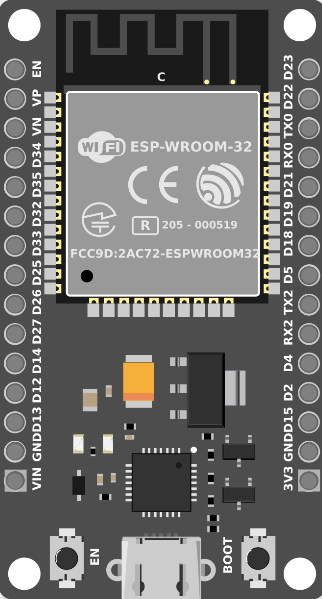
Pin Configuration and Descriptions
The ESP32 has a flexible pinout, with many pins serving multiple functions. Below is a table of the most commonly used pins and their descriptions:
| Pin Number | Pin Name | Functionality |
|---|---|---|
| 1 | EN | Enable pin (active high) |
| 2 | GPIO0 | General-purpose I/O, boot mode selection |
| 3 | GPIO2 | General-purpose I/O, ADC2 channel |
| 4 | GPIO4 | General-purpose I/O, ADC2 channel, PWM |
| 5 | GPIO5 | General-purpose I/O, ADC2 channel, PWM |
| 6-11 | GPIO12-19 | General-purpose I/O, ADC, PWM, UART, etc. |
| 12 | GPIO21 | I2C SDA, general-purpose I/O |
| 13 | GPIO22 | I2C SCL, general-purpose I/O |
| 14 | GPIO23 | SPI MOSI, general-purpose I/O |
| 15 | GPIO25 | DAC1, ADC2 channel, general-purpose I/O |
| 16 | GPIO26 | DAC2, ADC2 channel, general-purpose I/O |
| 17 | GPIO27 | ADC2 channel, general-purpose I/O |
| 18 | GPIO32 | ADC1 channel, general-purpose I/O |
| 19 | GPIO33 | ADC1 channel, general-purpose I/O |
| 20 | GPIO34-39 | ADC1 channels, input-only pins |
Note: Some GPIO pins are reserved for specific functions during boot or are input-only. Refer to the ESP32 datasheet for detailed pin multiplexing information.
Usage Instructions
The ESP32 can be used in a variety of circuits and projects. Below are the steps and best practices for using the ESP32 in your designs:
Basic Circuit Setup
- Power Supply: Connect the ESP32 to a stable 3.3V power source. Avoid exceeding 3.6V to prevent damage.
- Boot Mode: To upload code, connect GPIO0 to GND and reset the board. After uploading, disconnect GPIO0 from GND.
- Serial Communication: Use the UART pins (TX and RX) to communicate with a computer or other devices.
- Peripherals: Connect sensors, actuators, or other peripherals to the GPIO pins as needed. Ensure proper voltage levels and current limits.
Example: Blinking an LED with Arduino IDE
The ESP32 is compatible with the Arduino IDE, making it easy to program. Below is an example of how to blink an LED connected to GPIO2:
// Define the GPIO pin for the LED
#define LED_PIN 2

void setup() {
  // Set the LED pin as an output
  pinMode(LED_PIN, OUTPUT);
}

void loop() {
  // Turn the LED on
  digitalWrite(LED_PIN, HIGH);
  delay(1000); // Wait for 1 second

  // Turn the LED off
  digitalWrite(LED_PIN, LOW);
  delay(1000); // Wait for 1 second
}
Best Practices
- Use level shifters when interfacing with 5V devices to avoid damaging the ESP32.
- Decouple the power supply with capacitors (e.g., 10 µF and 0.1 µF) near the ESP32 to reduce noise.
- Avoid using ADC2 channels when Wi-Fi is active, as they share resources and may cause conflicts.
- Use deep sleep mode to conserve power in battery-operated projects.
Troubleshooting and FAQs
Common Issues and Solutions
ESP32 Not Detected by Computer
- Ensure the correct USB driver is installed (e.g., CP210x or CH340).
- Check the USB cable for data transfer capability (some cables are power-only).
Code Upload Fails
- Verify that GPIO0 is connected to GND during the upload process.
- Check the selected board and COM port in the Arduino IDE.
Wi-Fi Connection Issues
- Ensure the correct SSID and password are used in the code.
- Check for interference or weak signal strength.
Random Resets or Instability
- Verify that the power supply provides sufficient current (at least 500 mA).
- Add decoupling capacitors to stabilize the power supply.
FAQs
Q: Can the ESP32 operate on 5V?
A: No, the ESP32 operates on 3.3V. Applying 5V to its GPIO pins can damage the chip.
Q: How do I use Bluetooth on the ESP32?
A: The ESP32 supports both Bluetooth Classic and BLE. Use the BluetoothSerial or BLE libraries in the Arduino IDE to implement Bluetooth functionality.
Q: Can I use the ESP32 with a battery?
A: Yes, the ESP32 can be powered by a LiPo battery. Use a voltage regulator or a battery management module to ensure a stable 3.3V supply.
Q: What is the maximum Wi-Fi range of the ESP32?
A: The Wi-Fi range depends on the environment but typically extends up to 100 meters in open spaces.
By following this documentation, you can effectively integrate the ESP32 into your projects and troubleshoot common issues. For more advanced features, refer to the official ESP32 datasheet and programming guides.