How to Use charge controller: Examples, Pinouts, and Specs
Introduction
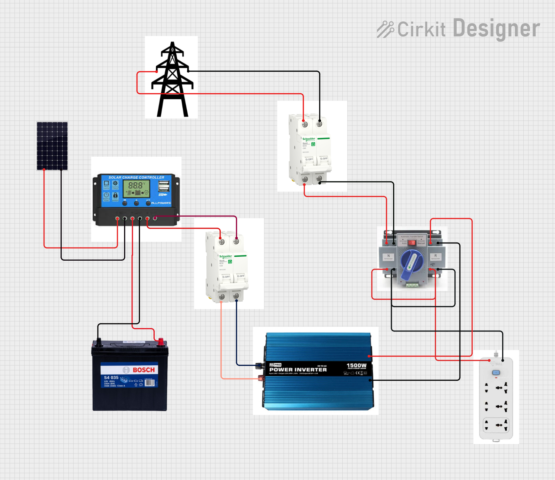
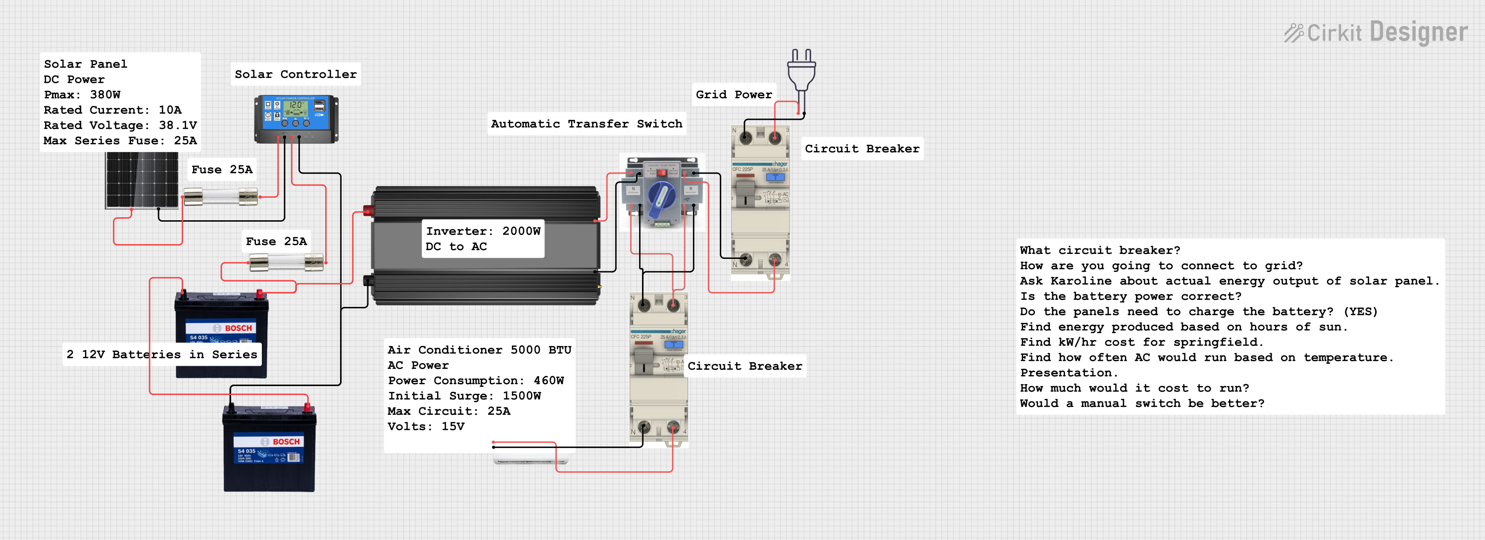
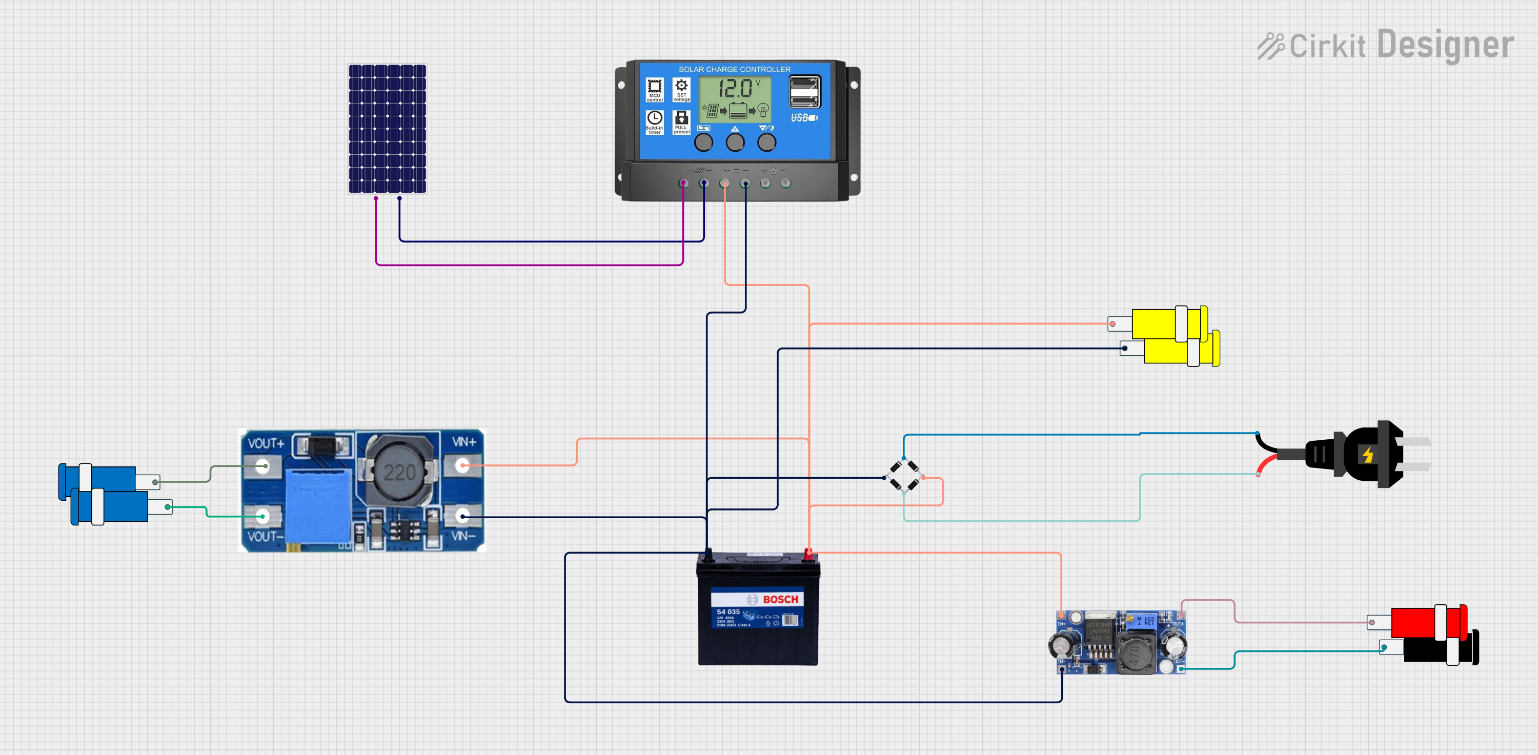
The DIY189 Solar Control charge controller is a device designed to regulate the voltage and current from a solar panel to a connected battery. Its primary function is to prevent overcharging, which can damage batteries, and to ensure optimal battery performance and longevity. This component is essential in solar power systems, acting as a safeguard for batteries and improving the overall efficiency of energy storage.
Explore Projects Built with charge controller
Explore Projects Built with charge controller
Common Applications and Use Cases
- Solar-powered home energy systems
- Off-grid solar installations
- Solar-powered lighting systems
- Portable solar charging setups
- Renewable energy research and development projects
Technical Specifications
The following table outlines the key technical details of the DIY189 Solar Control charge controller:
| Parameter | Value |
|---|---|
| Input Voltage Range | 12V to 24V DC |
| Maximum Input Current | 10A |
| Output Voltage Range | 12V or 24V (auto-detect) |
| Maximum Load Current | 10A |
| Efficiency | ≥ 95% |
| Operating Temperature | -20°C to 60°C |
| Battery Type Support | Lead-acid, Lithium-ion, LiFePO4 |
| Protection Features | Overcharge, Over-discharge, Short Circuit, Reverse Polarity |
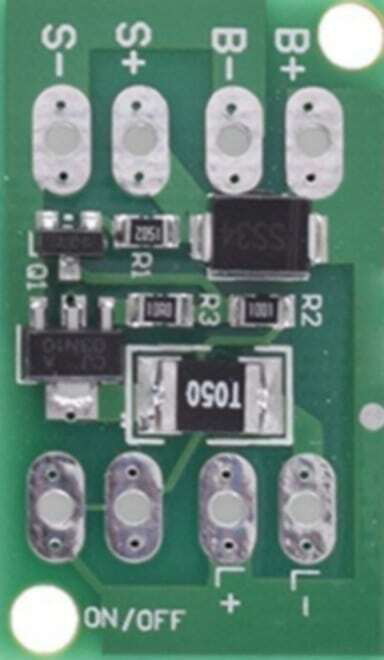
Pin Configuration and Descriptions
The DIY189 Solar Control charge controller has the following pin configuration:
| Pin Name | Description |
|---|---|
| PV+ | Positive terminal for solar panel input |
| PV- | Negative terminal for solar panel input |
| BAT+ | Positive terminal for battery connection |
| BAT- | Negative terminal for battery connection |
| LOAD+ | Positive terminal for load connection (e.g., lights, appliances) |
| LOAD- | Negative terminal for load connection |
Usage Instructions
How to Use the Charge Controller in a Circuit
- Connect the Solar Panel:
- Attach the positive terminal of the solar panel to the
PV+pin. - Attach the negative terminal of the solar panel to the
PV-pin.
- Attach the positive terminal of the solar panel to the
- Connect the Battery:
- Connect the positive terminal of the battery to the
BAT+pin. - Connect the negative terminal of the battery to the
BAT-pin.
- Connect the positive terminal of the battery to the
- Connect the Load (Optional):
- If you want to power a load directly from the charge controller, connect the load's positive terminal to the
LOAD+pin and the negative terminal to theLOAD-pin.
- If you want to power a load directly from the charge controller, connect the load's positive terminal to the
- Power On:
- Once all connections are secure, the charge controller will automatically detect the battery voltage and begin regulating the charge.
Important Considerations and Best Practices
- Battery Compatibility: Ensure the battery type is supported (e.g., Lead-acid, Lithium-ion, or LiFePO4).
- Voltage Matching: Verify that the solar panel's voltage and current ratings are within the charge controller's input range.
- Wiring: Use appropriately rated wires to handle the current without overheating.
- Placement: Install the charge controller in a well-ventilated area to prevent overheating.
- Polarity: Double-check all connections to avoid reverse polarity, which could damage the controller.
Arduino UNO Integration Example
The DIY189 Solar Control charge controller can be monitored using an Arduino UNO to track battery voltage and solar panel performance. Below is an example code snippet:
// Example: Monitor battery voltage using Arduino UNO
// Connect the BAT+ pin to an analog input pin (e.g., A0) via a voltage divider

const int batteryPin = A0; // Analog pin connected to BAT+ via voltage divider
float voltageDividerRatio = 5.0; // Adjust based on your resistor values
float referenceVoltage = 5.0; // Arduino's reference voltage (5V for most boards)

void setup() {
  Serial.begin(9600); // Initialize serial communication
  pinMode(batteryPin, INPUT); // Set the battery pin as input
}

void loop() {
  int rawValue = analogRead(batteryPin); // Read the analog value
  float batteryVoltage = (rawValue / 1023.0) * referenceVoltage * voltageDividerRatio;

  // Print the battery voltage to the Serial Monitor
  Serial.print("Battery Voltage: ");
  Serial.print(batteryVoltage);
  Serial.println(" V");

  delay(1000); // Wait for 1 second before the next reading
}
Note: Use a voltage divider circuit to scale down the battery voltage to a safe range for the Arduino's analog input (0-5V). Choose resistor values carefully to match the expected battery voltage.
Troubleshooting and FAQs
Common Issues and Solutions
No Output Voltage:
- Cause: Incorrect wiring or loose connections.
- Solution: Double-check all connections, ensuring proper polarity and secure terminals.
Battery Not Charging:
- Cause: Solar panel output is insufficient (e.g., low sunlight).
- Solution: Verify the solar panel's voltage and current output. Ensure it meets the charge controller's input requirements.
Overheating:
- Cause: High ambient temperature or excessive current draw.
- Solution: Place the charge controller in a well-ventilated area and ensure the load does not exceed the maximum current rating.
LED Indicators Not Working:
- Cause: Faulty charge controller or power supply issue.
- Solution: Check the input voltage from the solar panel and ensure it is within the specified range.
FAQs
Q: Can I use this charge controller with a 48V battery system?
A: No, the DIY189 Solar Control charge controller supports only 12V and 24V systems.Q: Does the charge controller support MPPT (Maximum Power Point Tracking)?
A: No, this model uses PWM (Pulse Width Modulation) for charge regulation.Q: How do I know if the battery is fully charged?
A: The charge controller's LED indicators will show the battery status. Refer to the user manual for specific LED behavior.Q: Can I connect multiple solar panels to this charge controller?
A: Yes, as long as the combined voltage and current of the panels do not exceed the controller's input ratings.
By following this documentation, users can effectively integrate the DIY189 Solar Control charge controller into their solar power systems for reliable and efficient energy management.