How to Use HW-958: Examples, Pinouts, and Specs
Introduction
The HW-958, manufactured by 宏维微 (part ID: ADS1120), is a high-performance electronic component designed for precision signal processing and power management applications. It is widely used in systems requiring accurate analog-to-digital conversion, such as sensor interfacing, industrial automation, and medical devices. Known for its reliability and efficiency, the HW-958 is an essential component in circuits where precise electrical signal handling is critical.
Explore Projects Built with HW-958


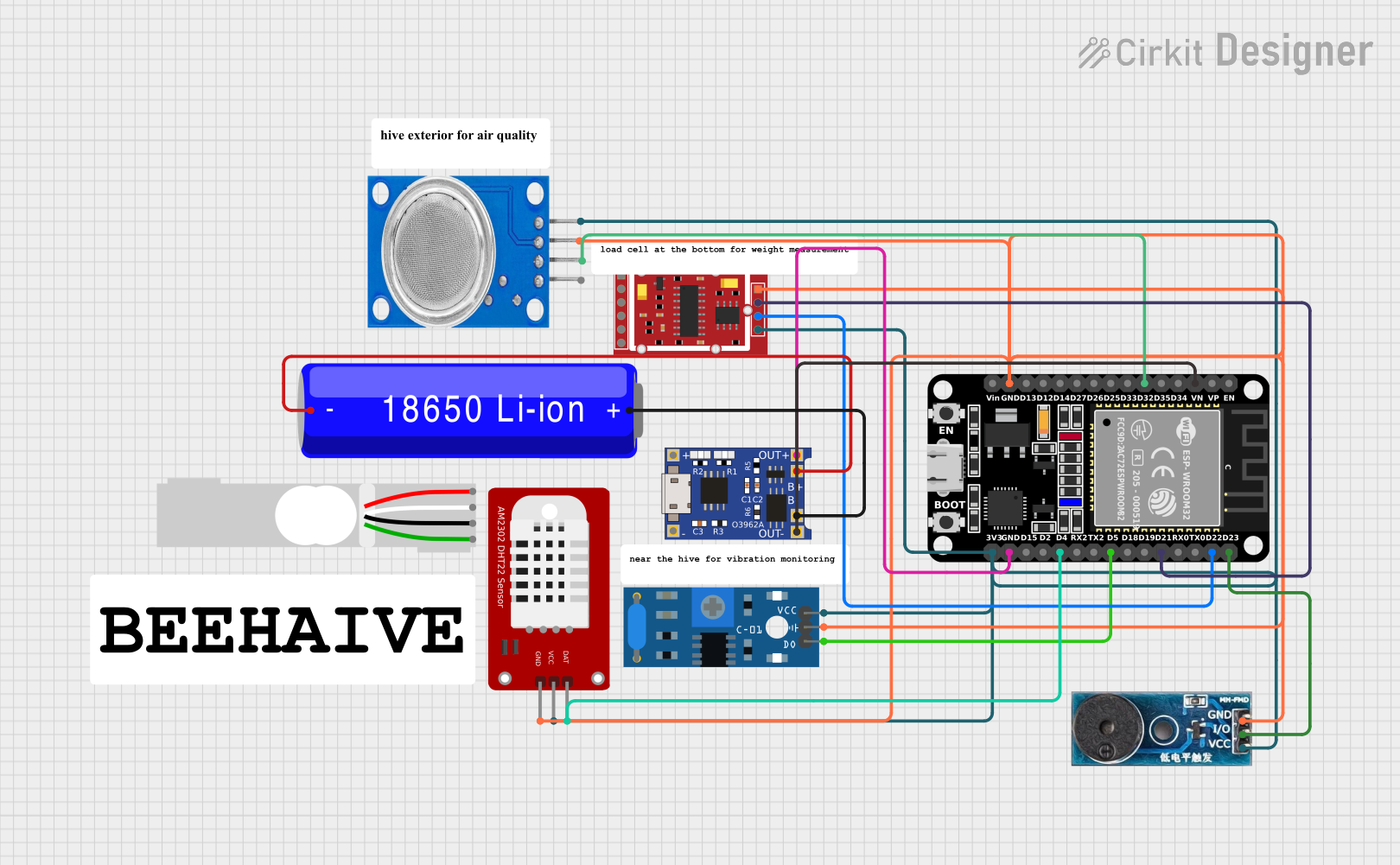
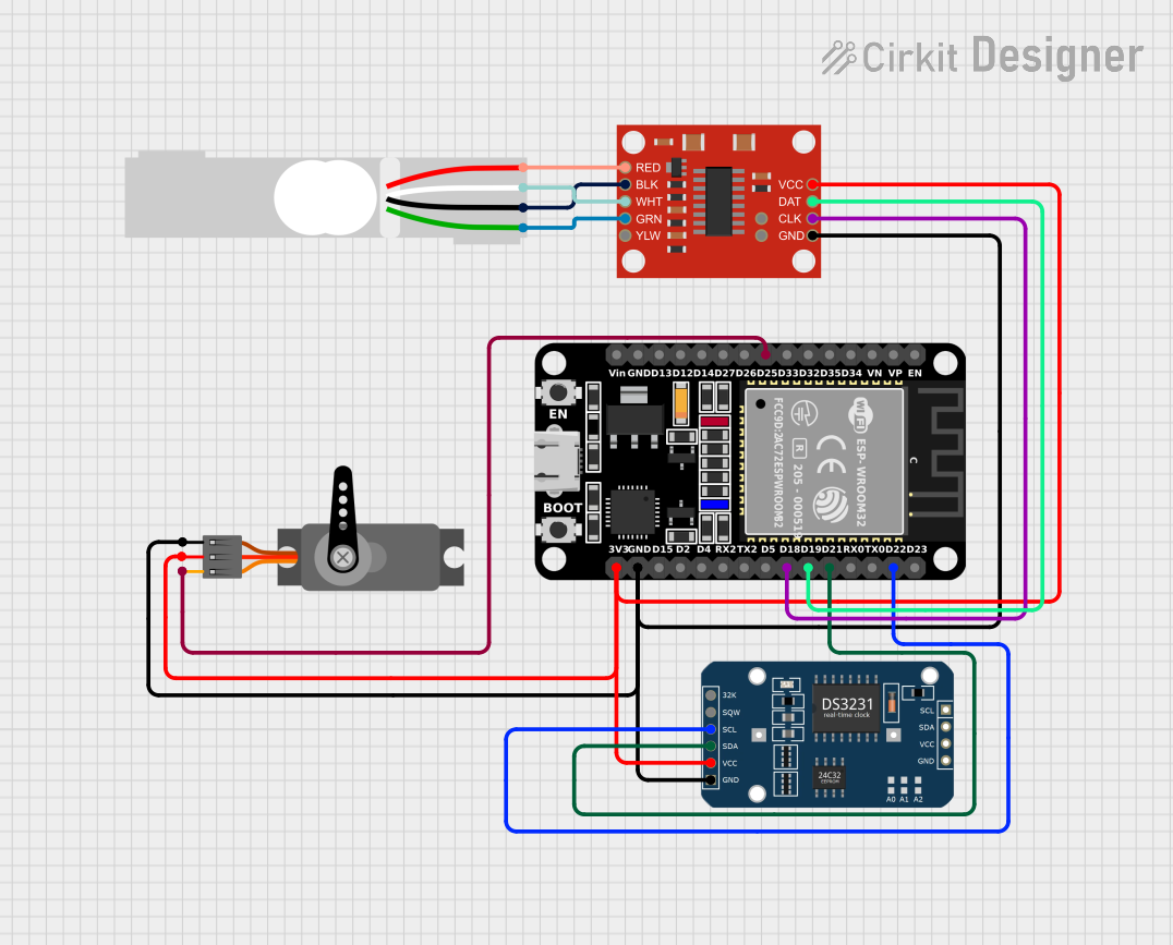
Explore Projects Built with HW-958
Common Applications
- Sensor data acquisition (e.g., temperature, pressure, or load sensors)
- Industrial process control systems
- Medical instrumentation
- Battery monitoring and power management
- Embedded systems requiring low-power, high-accuracy ADCs
Technical Specifications
The HW-958 is based on the ADS1120, a 16-bit, low-power, precision analog-to-digital converter (ADC). Below are its key technical details:
Key Specifications
| Parameter | Value |
|---|---|
| Resolution | 16-bit |
| Input Channels | 4 (multiplexed) |
| Operating Voltage Range | 2.3V to 5.5V |
| Power Consumption | 315 µA (typical) |
| Data Rate | Up to 2 kSPS |
| Input Impedance | >10 GΩ |
| Operating Temperature | -40°C to +125°C |
| Communication Interface | SPI (Serial Peripheral Interface) |
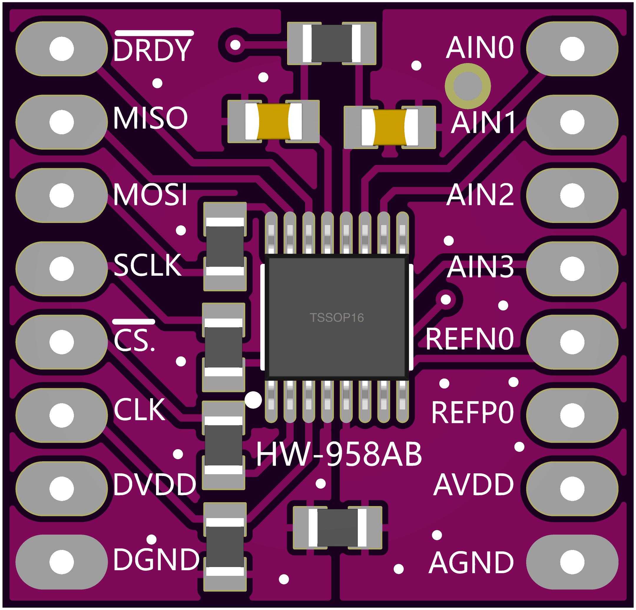
Pin Configuration and Descriptions
The HW-958 module typically features a 10-pin interface. Below is the pinout and description:
| Pin Number | Pin Name | Description |
|---|---|---|
| 1 | VDD | Power supply input (2.3V to 5.5V) |
| 2 | GND | Ground connection |
| 3 | SCLK | SPI clock input |
| 4 | DIN | SPI data input (MOSI) |
| 5 | DOUT/DRDY | SPI data output (MISO) / Data ready signal |
| 6 | CS | Chip select (active low) |
| 7 | AIN0 | Analog input channel 0 |
| 8 | AIN1 | Analog input channel 1 |
| 9 | AIN2 | Analog input channel 2 |
| 10 | AIN3 | Analog input channel 3 |
Usage Instructions
The HW-958 is straightforward to integrate into a circuit, especially for applications requiring analog-to-digital conversion. Below are the steps and best practices for using the component:
How to Use the HW-958 in a Circuit
- Power Supply: Connect the VDD pin to a stable power source (2.3V to 5.5V) and the GND pin to the ground.
- SPI Communication: Connect the SCLK, DIN, DOUT/DRDY, and CS pins to the corresponding SPI pins of your microcontroller.
- Analog Inputs: Connect the analog signals to be measured to the AIN0–AIN3 pins. Ensure the input voltage levels are within the ADC's input range.
- Configuration: Use SPI commands to configure the ADC settings, such as gain, data rate, and input channel selection.
- Data Acquisition: Read the converted digital data via the SPI interface. Monitor the DOUT/DRDY pin for data readiness.
Important Considerations
- Input Signal Conditioning: Use appropriate filters or amplifiers to condition the input signals before feeding them into the ADC.
- Power Supply Decoupling: Place a decoupling capacitor (e.g., 0.1 µF) close to the VDD pin to reduce noise.
- SPI Timing: Ensure the SPI clock frequency and timing meet the ADS1120's requirements.
- Temperature Effects: Operate the HW-958 within its specified temperature range to maintain accuracy.
Example Code for Arduino UNO
Below is an example of how to interface the HW-958 with an Arduino UNO using SPI:
#include <SPI.h>

// Pin definitions
const int CS_PIN = 10;  // Chip select pin for HW-958

void setup() {
  // Initialize SPI communication
  SPI.begin();
  pinMode(CS_PIN, OUTPUT);
  digitalWrite(CS_PIN, HIGH);  // Set CS pin high (inactive)

  Serial.begin(9600);  // Initialize serial communication for debugging
}

void loop() {
  // Example: Read data from HW-958
  digitalWrite(CS_PIN, LOW);  // Select the HW-958
  SPI.transfer(0x40);         // Send a command (e.g., read register 0x00)
  byte data = SPI.transfer(0x00);  // Read data from the HW-958
  digitalWrite(CS_PIN, HIGH);  // Deselect the HW-958

  Serial.print("Data: ");
  Serial.println(data, HEX);  // Print the received data in hexadecimal format

  delay(1000);  // Wait for 1 second before the next read
}
Notes on the Code
- Replace
0x40with the appropriate command for your application. - Ensure the SPI clock speed is compatible with the HW-958 (ADS1120).
Troubleshooting and FAQs
Common Issues and Solutions
No Data Output
- Cause: Incorrect SPI connections or configuration.
- Solution: Verify the SPI wiring and ensure the SPI settings (clock polarity, phase, and speed) match the HW-958's requirements.
Inaccurate Readings
- Cause: Noisy input signals or improper grounding.
- Solution: Use proper signal conditioning (e.g., filters) and ensure a solid ground connection.
Device Not Responding
- Cause: CS pin not toggled correctly.
- Solution: Ensure the CS pin is pulled low before sending SPI commands and pulled high afterward.
Overheating
- Cause: Exceeding the operating voltage or current limits.
- Solution: Check the power supply voltage and ensure it is within the specified range (2.3V to 5.5V).
FAQs
Q: Can the HW-958 handle differential inputs?
A: Yes, the HW-958 supports differential input configurations using its multiplexed input channels.
Q: What is the maximum sampling rate of the HW-958?
A: The maximum data rate is 2 kSPS, but lower rates can be configured for higher resolution.
Q: Is the HW-958 compatible with 3.3V systems?
A: Yes, the HW-958 operates within a voltage range of 2.3V to 5.5V, making it compatible with 3.3V systems.
Q: How do I reduce noise in my measurements?
A: Use proper shielding, grounding, and input signal filtering to minimize noise.
This documentation provides a comprehensive guide to understanding and using the HW-958 effectively in your projects.