Cirkit Designer
Your all-in-one circuit design IDE
Home /
Component Documentation
How to Use XBEE s2c: Examples, Pinouts, and Specs

 Design with XBEE s2c in Cirkit Designer
Introduction
The XBEE S2C, manufactured by Digi International (Part ID: XB24CAUIS-001), is a wireless communication module that utilizes the Zigbee protocol. This module is designed for creating mesh networks, making it an ideal choice for Internet of Things (IoT) applications. It offers reliable and low-power data transmission, which is essential for various applications such as home automation, industrial control, and remote monitoring.
Explore Projects Built with XBEE s2c
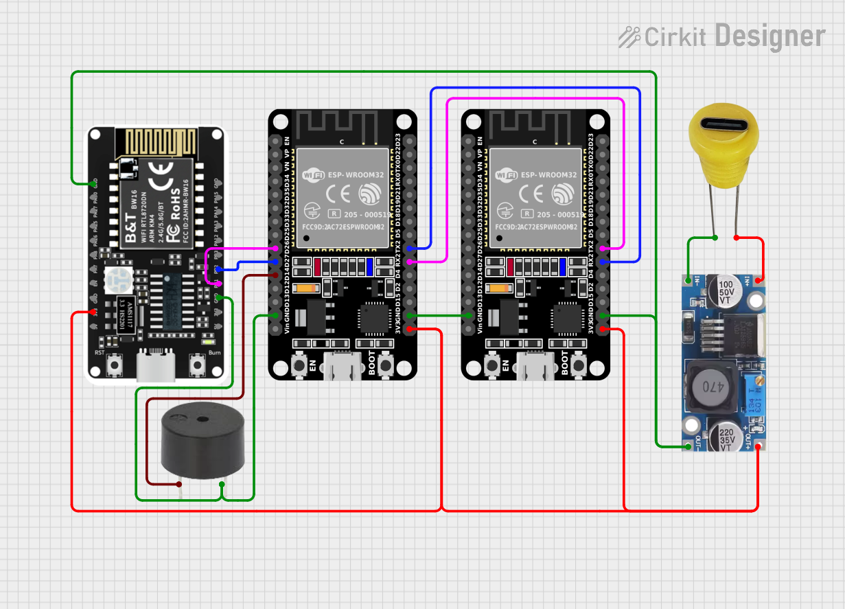
ESP32 and BW16-Kit-1 Microcontroller Communication Hub with Buzzer Notification

This circuit features two ESP32 microcontrollers configured to communicate with each other via serial connection, as indicated by the cross-connection of their TX2 and RX2 pins. A BW16-Kit-1 microcontroller is also included, interfacing with one of the ESP32s through pins D26 and D27. Power is supplied to the microcontrollers through a step-down buck converter connected to a 5V Type C DC socket, and a buzzer is driven by one of the ESP32s, potentially for audio signaling purposes.
 Open Project in Cirkit Designer
Satellite-Based Timing and Navigation System with SDR and Atomic Clock Synchronization

This circuit appears to be a complex system involving power supply management, GPS and timing synchronization, and data communication. It includes a SI-TEX G1 Satellite Compass for GPS data, an XHTF1021 Atomic Rubidium Clock for precise timing, and Ettus USRP B200 units for software-defined radio communication. Power is supplied through various SMPS units and distributed via terminal blocks and DC jacks. Data communication is facilitated by Beelink MINI S12 N95 computers, RS232 splitters, and a 1000BASE-T Media Converter for network connectivity. RF Directional Couplers are used to interface antennas with the USRP units, and the entire system is likely contained within cases for protection and organization.
 Open Project in Cirkit Designer
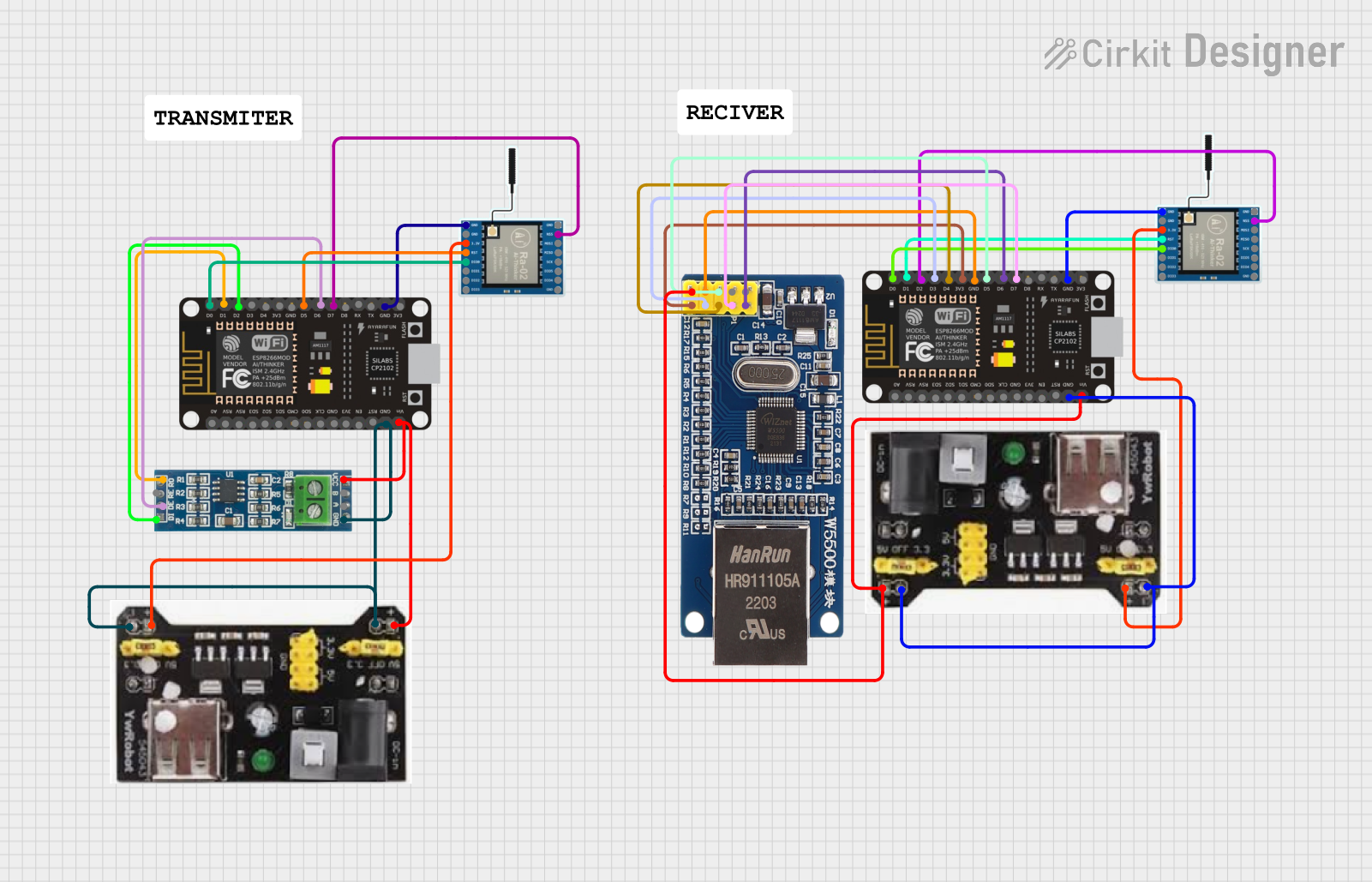
ESP8266 NodeMCU with LoRa and RS-485 Communication and Ethernet Connectivity

This circuit serves as a multi-protocol communication hub featuring two ESP8266 NodeMCUs for processing, each connected to a LoRa Ra-02 SX1278 for long-range wireless communication. One NodeMCU is also connected to an RS-485 module for serial communication and a W5500 Ethernet module for network connectivity, with MB102 modules supplying power.
 Open Project in Cirkit Designer
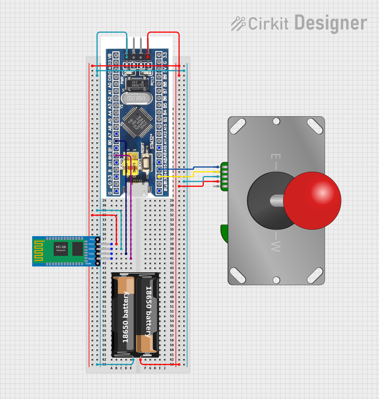
STM32F103C8T6 Bluetooth-Controlled Arcade Joystick Interface

This circuit features an STM32F103C8T6 microcontroller interfaced with a Bluetooth HC-06 module for wireless communication and an Adafruit Arcade Joystick for user input. The microcontroller's pins B0 and B10 are connected to the TXD and RXD pins of the Bluetooth module, enabling serial communication, while pins B14 and B15 interface with the joystick's directional controls. The circuit is powered by a battery, with power distribution managed through the microcontroller's 3.3V pin and common ground connections.
 Open Project in Cirkit Designer
Explore Projects Built with XBEE s2c

ESP32 and BW16-Kit-1 Microcontroller Communication Hub with Buzzer Notification
This circuit features two ESP32 microcontrollers configured to communicate with each other via serial connection, as indicated by the cross-connection of their TX2 and RX2 pins. A BW16-Kit-1 microcontroller is also included, interfacing with one of the ESP32s through pins D26 and D27. Power is supplied to the microcontrollers through a step-down buck converter connected to a 5V Type C DC socket, and a buzzer is driven by one of the ESP32s, potentially for audio signaling purposes.
 Open Project in Cirkit Designer
Satellite-Based Timing and Navigation System with SDR and Atomic Clock Synchronization
This circuit appears to be a complex system involving power supply management, GPS and timing synchronization, and data communication. It includes a SI-TEX G1 Satellite Compass for GPS data, an XHTF1021 Atomic Rubidium Clock for precise timing, and Ettus USRP B200 units for software-defined radio communication. Power is supplied through various SMPS units and distributed via terminal blocks and DC jacks. Data communication is facilitated by Beelink MINI S12 N95 computers, RS232 splitters, and a 1000BASE-T Media Converter for network connectivity. RF Directional Couplers are used to interface antennas with the USRP units, and the entire system is likely contained within cases for protection and organization.
 Open Project in Cirkit Designer
ESP8266 NodeMCU with LoRa and RS-485 Communication and Ethernet Connectivity
This circuit serves as a multi-protocol communication hub featuring two ESP8266 NodeMCUs for processing, each connected to a LoRa Ra-02 SX1278 for long-range wireless communication. One NodeMCU is also connected to an RS-485 module for serial communication and a W5500 Ethernet module for network connectivity, with MB102 modules supplying power.
 Open Project in Cirkit Designer
STM32F103C8T6 Bluetooth-Controlled Arcade Joystick Interface
This circuit features an STM32F103C8T6 microcontroller interfaced with a Bluetooth HC-06 module for wireless communication and an Adafruit Arcade Joystick for user input. The microcontroller's pins B0 and B10 are connected to the TXD and RXD pins of the Bluetooth module, enabling serial communication, while pins B14 and B15 interface with the joystick's directional controls. The circuit is powered by a battery, with power distribution managed through the microcontroller's 3.3V pin and common ground connections.
 Open Project in Cirkit Designer
Technical Specifications
Key Technical Details
| Parameter | Value |
|---|---|
| Protocol | Zigbee |
| Frequency | 2.4 GHz |
| Data Rate | Up to 250 kbps |
| Supply Voltage | 2.1V to 3.6V |
| Transmit Current | 45 mA (typical) |
| Receive Current | 31 mA (typical) |
| Sleep Current | < 1 µA |
| Operating Temperature | -40°C to 85°C |
| Range | Up to 120 meters (indoor) |
| Antenna | Integrated PCB antenna |
Pin Configuration and Descriptions
| Pin | Name | Description |
|---|---|---|
| 1 | VCC | Power supply (2.1V to 3.6V) |
| 2 | DOUT | UART Data Out |
| 3 | DIN/CONFIG | UART Data In / Configuration |
| 4 | DIO12 | Digital I/O 12 |
| 5 | RESET | Module Reset (Active Low) |
| 6 | RSSI | Received Signal Strength Indicator |
| 7 | PWM0 | PWM Output 0 |
| 8 | PWM1 | PWM Output 1 |
| 9 | DIO11 | Digital I/O 11 |
| 10 | DIO10 | Digital I/O 10 |
| 11 | DIO9 | Digital I/O 9 |
| 12 | DIO8 | Digital I/O 8 |
| 13 | DIO7 | Digital I/O 7 |
| 14 | VREF | Voltage Reference for A/D inputs |
| 15 | DIO6 | Digital I/O 6 |
| 16 | DIO5 | Digital I/O 5 |
| 17 | DIO4 | Digital I/O 4 |
| 18 | DIO3 | Digital I/O 3 |
| 19 | DIO2 | Digital I/O 2 |
| 20 | DIO1 | Digital I/O 1 |
| 21 | DIO0/AD0 | Digital I/O 0 / Analog Input 0 |
| 22 | GND | Ground |
Usage Instructions
How to Use the XBEE S2C in a Circuit
- Power Supply: Connect the VCC pin to a 3.3V power supply and the GND pin to the ground.
- UART Communication: Connect the DOUT pin to the RX pin of your microcontroller and the DIN/CONFIG pin to the TX pin of your microcontroller.
- Reset: Optionally, connect the RESET pin to a digital I/O pin of your microcontroller to allow for software resets.
- Antenna: Ensure the module's integrated PCB antenna is not obstructed for optimal signal strength.
Important Considerations and Best Practices
- Power Supply: Ensure a stable 3.3V power supply to avoid communication issues.
- Antenna Placement: Avoid placing the module near metal objects or inside metal enclosures to prevent signal attenuation.
- Configuration: Use Digi's XCTU software for configuring the module's parameters such as PAN ID, channel, and baud rate.
- Sleep Mode: Utilize the module's sleep mode to save power in battery-operated applications.
Example Code for Arduino UNO
#include <SoftwareSerial.h>

// Define RX and TX pins for SoftwareSerial
SoftwareSerial XBee(2, 3); // RX, TX

void setup() {
  // Start the hardware serial communication
  Serial.begin(9600);
  // Start the software serial communication
  XBee.begin(9600);
}

void loop() {
  if (XBee.available()) {
    // Read data from XBee and send it to Serial Monitor
    char data = XBee.read();
    Serial.print(data);
  }

  if (Serial.available()) {
    // Read data from Serial Monitor and send it to XBee
    char data = Serial.read();
    XBee.print(data);
  }
}
Troubleshooting and FAQs
Common Issues Users Might Face
No Communication Between Modules:
- Solution: Ensure both modules are configured with the same PAN ID and channel. Verify the baud rate settings match between the module and the microcontroller.
Weak Signal Strength:
- Solution: Check for obstructions near the module's antenna. Ensure the module is placed in an open area for better signal propagation.
Module Not Responding:
- Solution: Verify the power supply voltage is within the specified range. Check the connections, especially the ground and power lines.
Solutions and Tips for Troubleshooting
- Use XCTU Software: Utilize Digi's XCTU software to test and configure the module. It provides tools for network discovery, range testing, and firmware updates.
- Check Connections: Double-check all wiring connections, especially the UART connections (DOUT to RX and DIN/CONFIG to TX).
- Firmware Update: Ensure the module's firmware is up to date using the XCTU software.
By following this documentation, users can effectively integrate the XBEE S2C module into their projects, ensuring reliable and efficient wireless communication.