How to Use PIC16F877A: Examples, Pinouts, and Specs
Introduction
The PIC16F877A is an 8-bit microcontroller developed by Microchip Technology. It features a 14-bit instruction set architecture, 40 pins, 368 bytes of RAM, and 256 bytes of EEPROM. This microcontroller is widely recognized for its versatility, ease of programming, and robust set of integrated peripherals, including timers, analog-to-digital converters (ADCs), and serial communication interfaces.
Explore Projects Built with PIC16F877A


Explore Projects Built with PIC16F877A
Common Applications and Use Cases
- Embedded systems and IoT devices
- Industrial automation and control systems
- Home automation projects
- Data acquisition systems
- Robotics and motor control
- Educational and prototyping purposes
Technical Specifications
Below are the key technical details of the PIC16F877A microcontroller:
| Parameter | Value |
|---|---|
| Architecture | 8-bit |
| Instruction Set | 14-bit |
| Operating Voltage | 2.0V to 5.5V |
| Program Memory (Flash) | 14 KB |
| Data Memory (RAM) | 368 bytes |
| EEPROM | 256 bytes |
| I/O Pins | 33 |
| Timers | 3 (Timer0, Timer1, Timer2) |
| ADC Resolution | 10-bit |
| ADC Channels | 8 |
| Communication Interfaces | USART, SPI, I2C |
| Oscillator Frequency | Up to 20 MHz |
| Package Types | DIP-40, PLCC-44, TQFP-44 |
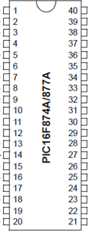
Pin Configuration and Descriptions
The PIC16F877A has 40 pins, with the following pin configuration:
| Pin Number | Pin Name | Description |
|---|---|---|
| 1 | MCLR/VPP | Master Clear (Reset) input or programming voltage |
| 2-7 | RA0-RA5 | Port A: Analog/Digital I/O |
| 8 | VSS | Ground (0V reference) |
| 9-10 | OSC1/OSC2 | Oscillator input/output |
| 11-18 | RB0-RB7 | Port B: Digital I/O |
| 19 | VDD | Positive supply voltage |
| 20-27 | RC0-RC7 | Port C: Digital I/O |
| 28-33 | RD0-RD7 | Port D: Digital I/O |
| 34-40 | RE0-RE2, VSS, VDD | Port E: Digital I/O, Ground, and Power Supply |
For a complete pinout diagram, refer to the official datasheet.
Usage Instructions
How to Use the PIC16F877A in a Circuit
- Power Supply: Connect the VDD pin to a 5V power source and the VSS pin to ground.
- Oscillator Setup: Connect an external crystal oscillator (e.g., 4 MHz) between OSC1 and OSC2 pins, along with two capacitors (typically 22 pF) to stabilize the clock signal.
- Reset Circuit: Connect a pull-up resistor (10 kΩ) to the MCLR pin for proper reset functionality.
- I/O Configuration: Configure the I/O pins (RA, RB, RC, RD, RE) as input or output in the software.
- Programming: Use an ICSP (In-Circuit Serial Programming) tool to upload your program to the microcontroller.
Important Considerations and Best Practices
- Ensure the operating voltage is within the specified range (2.0V to 5.5V).
- Use decoupling capacitors (e.g., 0.1 µF) near the power pins to reduce noise.
- Avoid leaving unused pins floating; connect them to ground or configure them as outputs.
- When using ADC functionality, ensure the reference voltage is stable and within the specified range.
- Use proper pull-up or pull-down resistors for input pins to avoid erratic behavior.
Example Code for Arduino UNO Integration
The PIC16F877A can communicate with an Arduino UNO via serial communication. Below is an example of how to send data from the Arduino to the PIC16F877A:
Arduino Code
void setup() {
  Serial.begin(9600); // Initialize serial communication at 9600 baud
}

void loop() {
  Serial.println("Hello, PIC16F877A!"); // Send data to the PIC
  delay(1000); // Wait for 1 second
}
PIC16F877A Code (Using MPLAB XC8 Compiler)
#include <xc.h>

// Configuration bits
#pragma config FOSC = XT        // Oscillator Selection (XT oscillator)
#pragma config WDTE = OFF       // Watchdog Timer Enable (WDT disabled)
#pragma config PWRTE = ON       // Power-up Timer Enable
#pragma config BOREN = ON       // Brown-out Reset Enable
#pragma config LVP = OFF        // Low-Voltage Programming Disable
#pragma config CPD = OFF        // Data EEPROM Memory Code Protection
#pragma config WRT = OFF        // Flash Program Memory Write Enable
#pragma config CP = OFF         // Flash Program Memory Code Protection

#define _XTAL_FREQ 4000000      // Define the oscillator frequency (4 MHz)

void UART_Init() {
    TRISC6 = 0; // TX pin as output
    TRISC7 = 1; // RX pin as input
    SPBRG = 25; // Baud rate = 9600 for 4 MHz clock
    TXEN = 1;   // Enable transmission
    SPEN = 1;   // Enable serial port
    CREN = 1;   // Enable continuous reception
}

void UART_Write(char data) {
    while (!TXIF); // Wait until the transmit buffer is empty
    TXREG = data;  // Transmit the data
}

void main() {
    UART_Init(); // Initialize UART
    while (1) {
        UART_Write('H'); // Send 'H'
        UART_Write('i'); // Send 'i'
        UART_Write('\n'); // Send newline
        __delay_ms(1000); // Wait for 1 second
    }
}
Troubleshooting and FAQs
Common Issues and Solutions
Microcontroller Not Responding
- Cause: Incorrect power supply or oscillator configuration.
- Solution: Verify the power connections and ensure the oscillator circuit is properly set up.
Serial Communication Not Working
- Cause: Mismatched baud rates between devices.
- Solution: Ensure both the PIC16F877A and the external device (e.g., Arduino) are configured to use the same baud rate.
ADC Produces Incorrect Values
- Cause: Unstable reference voltage or improper pin configuration.
- Solution: Use a stable reference voltage and configure the ADC pins correctly in the software.
Program Upload Fails
- Cause: Faulty ICSP connection or incorrect programming settings.
- Solution: Check the ICSP connections and ensure the programmer is configured for the PIC16F877A.
FAQs
Q: Can the PIC16F877A operate without an external oscillator?
A: No, the PIC16F877A requires an external oscillator or clock source to function.Q: How do I protect the EEPROM data from accidental overwrites?
A: Use software routines to implement write protection and avoid unnecessary EEPROM writes.Q: What is the maximum clock frequency supported by the PIC16F877A?
A: The maximum clock frequency is 20 MHz.Q: Can I use the PIC16F877A for low-power applications?
A: Yes, the PIC16F877A supports low-power modes such as Sleep mode to reduce power consumption.