How to Use ESP32 DEV KIT: Examples, Pinouts, and Specs
Introduction
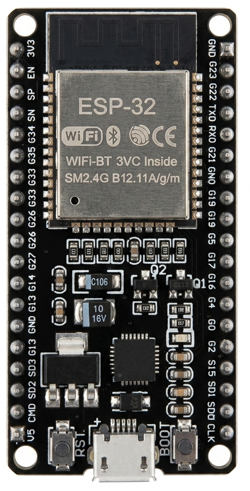
The ESP32 DEV KIT, manufactured by Espressif Systems (Part ID: ESP), is a versatile microcontroller development board designed for IoT projects and prototyping. It features built-in Wi-Fi and Bluetooth capabilities, making it an excellent choice for wireless communication applications. With its powerful dual-core processor, ample GPIO pins, and support for various peripherals, the ESP32 DEV KIT is widely used in smart home devices, wearable electronics, and industrial automation.
Explore Projects Built with ESP32 DEV KIT


Explore Projects Built with ESP32 DEV KIT
Common Applications
- IoT (Internet of Things) devices
- Home automation systems
- Wireless sensor networks
- Wearable technology
- Robotics and automation
- Prototyping and educational projects
Technical Specifications
The ESP32 DEV KIT is built around the ESP32 microcontroller, which integrates a dual-core processor, wireless communication modules, and a variety of peripherals.
Key Technical Details
| Parameter | Specification |
|---|---|
| Microcontroller | ESP32 (dual-core Xtensa LX6 CPU) |
| Clock Speed | Up to 240 MHz |
| Flash Memory | 4 MB (varies by model) |
| SRAM | 520 KB |
| Wireless Connectivity | Wi-Fi 802.11 b/g/n, Bluetooth 4.2 |
| Operating Voltage | 3.3V |
| Input Voltage (VIN) | 5V (via USB or external power supply) |
| GPIO Pins | 30-36 (varies by board version) |
| ADC Channels | Up to 18 |
| DAC Channels | 2 |
| Communication Interfaces | UART, SPI, I2C, I2S, CAN, PWM |
| Power Consumption | Ultra-low power (varies by mode) |
| Dimensions | ~25.4mm x 50.8mm |
Pin Configuration and Descriptions
The ESP32 DEV KIT typically features a 30-pin or 38-pin layout. Below is a table describing the key pins:
| Pin Name | Pin Number | Description |
|---|---|---|
| VIN | 1 | Input voltage (5V) for powering the board via an external source. |
| GND | Multiple | Ground pins for completing the circuit. |
| 3V3 | 2 | Regulated 3.3V output for powering external components. |
| EN | 3 | Enable pin; pulling it low resets the chip. |
| GPIO0 | 4 | General-purpose I/O pin; used for boot mode selection during programming. |
| GPIO2 | 5 | General-purpose I/O pin; often used for onboard LED. |
| GPIO12-39 | Varies | General-purpose I/O pins with multiple functions (ADC, PWM, I2C, etc.). |
| TXD0 | 6 | UART0 transmit pin for serial communication. |
| RXD0 | 7 | UART0 receive pin for serial communication. |
| ADC1_CH0 | 8 | Analog-to-digital converter channel 0. |
| DAC1 | 9 | Digital-to-analog converter channel 1. |
Note: Pin numbers and functions may vary slightly depending on the specific ESP32 DEV KIT model.
Usage Instructions
How to Use the ESP32 DEV KIT in a Circuit
Powering the Board:
- Connect the ESP32 DEV KIT to your computer via a micro-USB cable for power and programming.
- Alternatively, supply 5V to the VIN pin or 3.3V to the 3V3 pin for external power.
Programming the Board:
- Install the Arduino IDE and add the ESP32 board support package.
- Select the appropriate ESP32 board model under
Tools > Board. - Connect the board to your computer and select the correct COM port.
Connecting Peripherals:
- Use the GPIO pins to connect sensors, actuators, or other peripherals.
- Ensure that the voltage levels of connected devices are compatible with the ESP32 (3.3V logic).
Uploading Code:
- Write your code in the Arduino IDE or another supported environment.
- Click the upload button to flash the code to the ESP32 DEV KIT.
Example Code: Blinking an LED
The following example demonstrates how to blink an LED connected to GPIO2:
// Define the GPIO pin where the LED is connected
const int ledPin = 2;

void setup() {
  // Set the LED pin as an output
  pinMode(ledPin, OUTPUT);
}

void loop() {
  // Turn the LED on
  digitalWrite(ledPin, HIGH);
  delay(1000); // Wait for 1 second

  // Turn the LED off
  digitalWrite(ledPin, LOW);
  delay(1000); // Wait for 1 second
}
Important Considerations
- Voltage Levels: The ESP32 operates at 3.3V logic. Avoid connecting 5V signals directly to its GPIO pins.
- Boot Mode: Ensure GPIO0 is pulled low during programming to enter boot mode.
- Power Supply: Use a stable power source to avoid unexpected resets or malfunctions.
Troubleshooting and FAQs
Common Issues
The board is not detected by the computer:
- Ensure the USB cable is functional and supports data transfer.
- Install the correct USB-to-serial driver for the ESP32.
Code upload fails:
- Check that the correct board and COM port are selected in the Arduino IDE.
- Hold the BOOT button on the ESP32 DEV KIT while uploading the code.
Wi-Fi connection issues:
- Verify the SSID and password in your code.
- Ensure the router is within range and supports 2.4 GHz Wi-Fi.
GPIO pin not working:
- Confirm that the pin is not reserved for other functions (e.g., boot mode).
- Check for wiring errors or short circuits.
FAQs
Q: Can I power the ESP32 DEV KIT with a battery?
A: Yes, you can use a 3.7V LiPo battery connected to the 3V3 pin or a 5V source connected to the VIN pin.
Q: How do I reset the ESP32 DEV KIT?
A: Press the onboard RESET button or pull the EN pin low momentarily.
Q: Can the ESP32 DEV KIT handle 5V logic?
A: No, the ESP32 operates at 3.3V logic. Use a level shifter if interfacing with 5V devices.
Q: How do I use Bluetooth on the ESP32?
A: The ESP32 supports both Bluetooth Classic and BLE. Use the BluetoothSerial or BLE libraries in the Arduino IDE to implement Bluetooth functionality.
By following this documentation, you can effectively utilize the ESP32 DEV KIT for a wide range of applications.