Cirkit Designer Logo
Cirkit Designer
Your all-in-one circuit design IDE
Home / 
Component Documentation

How to Use Photodiode: Examples, Pinouts, and Specs

Image of Photodiode
Cirkit Designer LogoDesign with Photodiode in Cirkit Designer

Introduction

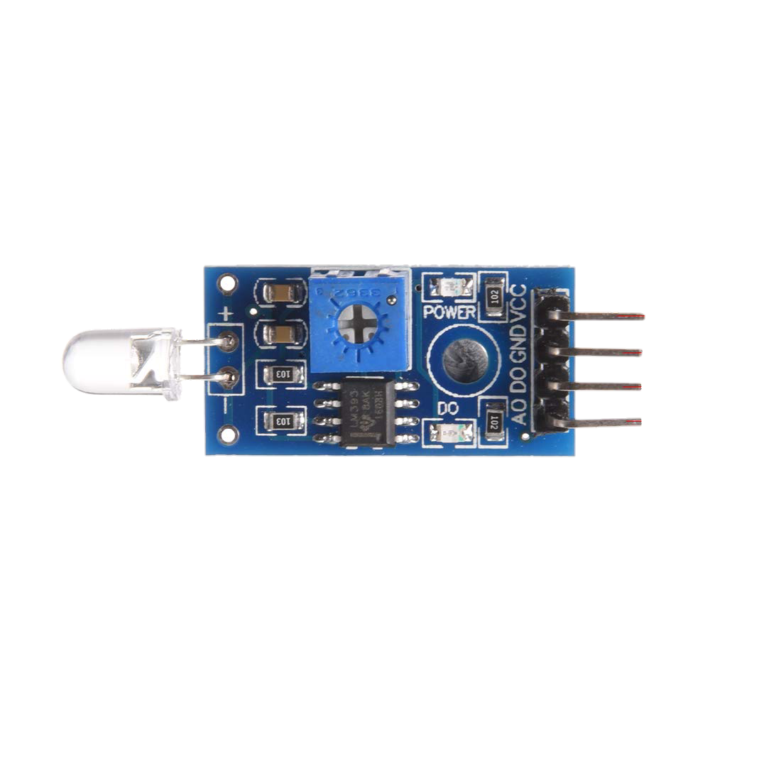
A photodiode is a semiconductor device that converts light into an electrical current. It is sensitive to light and operates in reverse bias, meaning that it allows current to flow when it is exposed to light. The current flow is directly proportional to the intensity of the light falling on it, making photodiodes useful for light detection and measurement applications.

Common applications of photodiodes include:

  • Ambient light sensing
  • Optical communication
  • Laser range finding
  • Safety equipment (smoke detectors)
  • Medical devices (pulse oximeters)

Explore Projects Built with Photodiode

Use Cirkit Designer to design, explore, and prototype these projects online. Some projects support real-time simulation. Click "Open Project" to start designing instantly!
Arduino Nano-Based Light Intensity Data Logger with Op-Amp Signal Conditioning
Image of TEST: A project utilizing Photodiode in a practical application
This circuit is designed to detect light intensity using a photodiode and convert the signal into a readable voltage using a Transimpedance Amplifier (TIA) configuration with an LM358 Op-Amp. The resistor and capacitor form a feedback network for the TIA, which outputs a voltage proportional to the light intensity to the Arduino Nano's analog input (A0). The Arduino Nano is programmed to read this analog voltage, convert it to a digital value, and output the result over serial communication for monitoring or further processing.
Cirkit Designer LogoOpen Project in Cirkit Designer
Arduino Nano-Based Light Sensing Circuit with LED Indicator
Image of Copy of LED yellow 2 pin mood light: A project utilizing Photodiode in a practical application
This circuit is designed to measure light intensity using a photodiode and a resistor to create a voltage divider, with the signal read by the Arduino Nano's A0 pin. A yellow LED is connected to the D2 pin, potentially serving as an indicator. The 9V battery powers the circuit, and the Arduino's code is yet to be implemented for specific functionality.
Cirkit Designer LogoOpen Project in Cirkit Designer
Arduino UNO-Based Light-Sensitive LED Controller
Image of Led_sensoreLuce: A project utilizing Photodiode in a practical application
This circuit is designed to detect light levels using a photodiode and control an LED based on the detected light. The Arduino UNO reads the voltage across the photodiode connected to its analog pin A0 and turns on the LED connected to digital pin D3 through a 220 Ohm resistor if the light level falls below a predefined threshold. The photodiode is powered by the Arduino's 5V output, and the LED's current is limited by the resistor.
Cirkit Designer LogoOpen Project in Cirkit Designer
Arduino UNO Light Sensor Circuit
Image of LDR circuit: A project utilizing Photodiode in a practical application
This circuit is designed to measure light intensity using a photocell (LDR) connected to an Arduino UNO. The photocell forms part of a voltage divider with a fixed resistor, and the resulting voltage is read by the Arduino's analog input A0. The purpose of the circuit is likely to monitor environmental light levels, which can be processed and utilized by the Arduino for various applications such as adjusting the brightness of a display or controlling lights.
Cirkit Designer LogoOpen Project in Cirkit Designer

Explore Projects Built with Photodiode

Use Cirkit Designer to design, explore, and prototype these projects online. Some projects support real-time simulation. Click "Open Project" to start designing instantly!
Image of TEST: A project utilizing Photodiode in a practical application
Arduino Nano-Based Light Intensity Data Logger with Op-Amp Signal Conditioning
This circuit is designed to detect light intensity using a photodiode and convert the signal into a readable voltage using a Transimpedance Amplifier (TIA) configuration with an LM358 Op-Amp. The resistor and capacitor form a feedback network for the TIA, which outputs a voltage proportional to the light intensity to the Arduino Nano's analog input (A0). The Arduino Nano is programmed to read this analog voltage, convert it to a digital value, and output the result over serial communication for monitoring or further processing.
Cirkit Designer LogoOpen Project in Cirkit Designer
Image of Copy of LED yellow 2 pin mood light: A project utilizing Photodiode in a practical application
Arduino Nano-Based Light Sensing Circuit with LED Indicator
This circuit is designed to measure light intensity using a photodiode and a resistor to create a voltage divider, with the signal read by the Arduino Nano's A0 pin. A yellow LED is connected to the D2 pin, potentially serving as an indicator. The 9V battery powers the circuit, and the Arduino's code is yet to be implemented for specific functionality.
Cirkit Designer LogoOpen Project in Cirkit Designer
Image of Led_sensoreLuce: A project utilizing Photodiode in a practical application
Arduino UNO-Based Light-Sensitive LED Controller
This circuit is designed to detect light levels using a photodiode and control an LED based on the detected light. The Arduino UNO reads the voltage across the photodiode connected to its analog pin A0 and turns on the LED connected to digital pin D3 through a 220 Ohm resistor if the light level falls below a predefined threshold. The photodiode is powered by the Arduino's 5V output, and the LED's current is limited by the resistor.
Cirkit Designer LogoOpen Project in Cirkit Designer
Image of LDR circuit: A project utilizing Photodiode in a practical application
Arduino UNO Light Sensor Circuit
This circuit is designed to measure light intensity using a photocell (LDR) connected to an Arduino UNO. The photocell forms part of a voltage divider with a fixed resistor, and the resulting voltage is read by the Arduino's analog input A0. The purpose of the circuit is likely to monitor environmental light levels, which can be processed and utilized by the Arduino for various applications such as adjusting the brightness of a display or controlling lights.
Cirkit Designer LogoOpen Project in Cirkit Designer

Technical Specifications

Key Technical Details

  • Material: Silicon, Germanium, or other semiconductor materials
  • Spectral Response: Typically from 200 nm to 1100 nm (varies by material)
  • Reverse Voltage: Varies by model (e.g., 5V, 10V, 100V)
  • Dark Current: The current through the photodiode in the absence of light; typically in the nanoampere range
  • Responsivity: The ratio of the photocurrent to the incident light power, measured in A/W
  • Capacitance: Varies with reverse voltage and area of the photodiode; typically in the picofarads (pF) range
  • Package: Various (e.g., through-hole, surface-mount, module)

Pin Configuration and Descriptions

Pin Number Description
1 Anode (+)
2 Cathode (-)

Usage Instructions

How to Use the Photodiode in a Circuit

  1. Reverse Bias Connection: Connect the anode to a negative potential and the cathode to a positive potential relative to the anode.
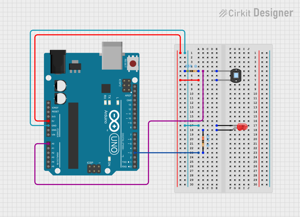
  2. Load Resistor: Place a load resistor (RL) in series with the photodiode to convert the photocurrent to a voltage.
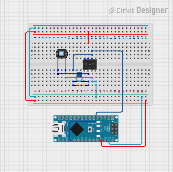
  3. Amplification: Use an operational amplifier (op-amp) in a transimpedance configuration to convert the current to a voltage with higher gain if needed.
  4. Filtering: Add a capacitor in parallel with the load resistor to filter out high-frequency noise.

Important Considerations and Best Practices

  • Reverse Bias Voltage: Ensure that the reverse bias voltage does not exceed the maximum rating to prevent damage.
  • Ambient Light: Be aware of ambient light that may affect measurements; use shielding if necessary.
  • Temperature Effects: Consider the temperature coefficient as it may affect the photodiode's performance.
  • Calibration: Calibrate the system for accurate light intensity measurements.

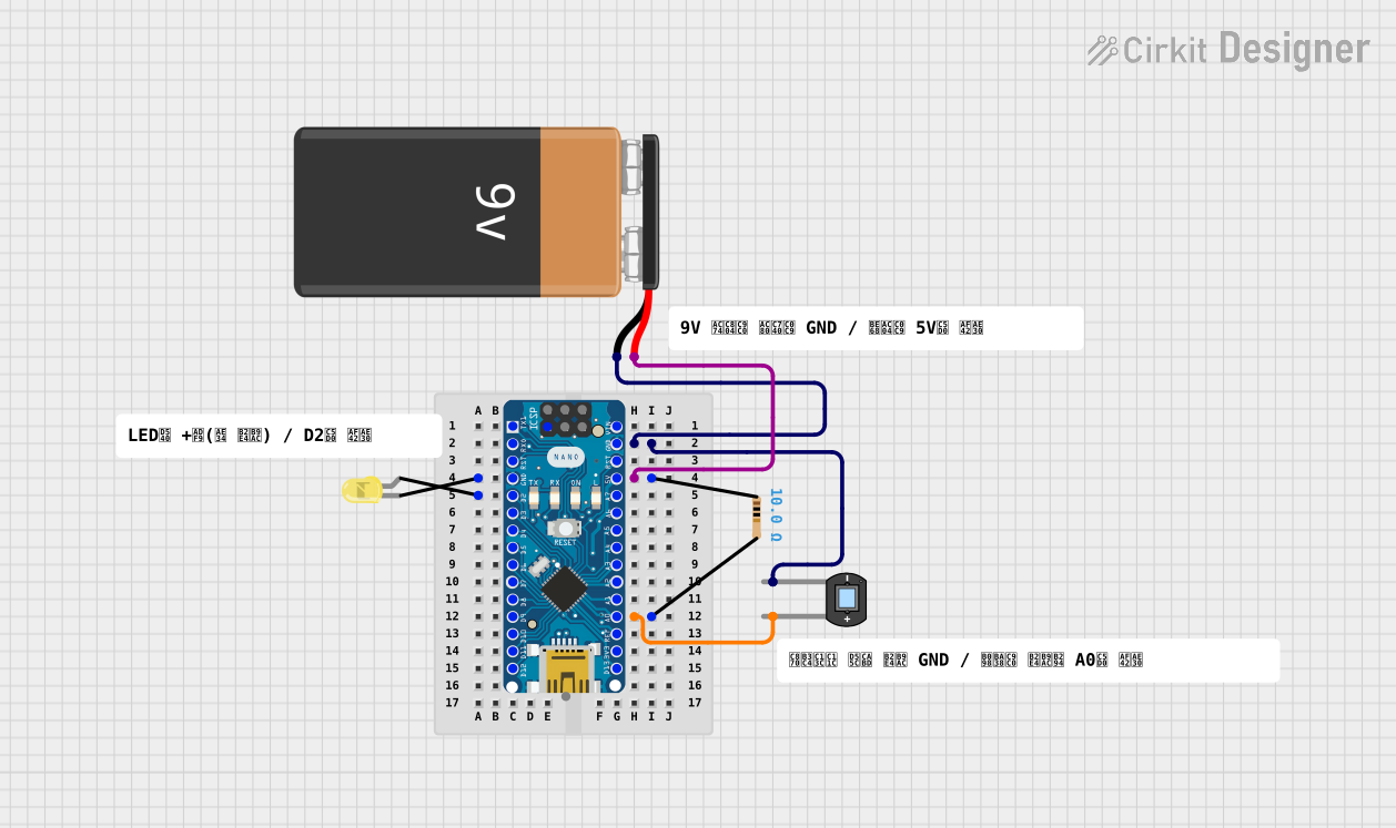
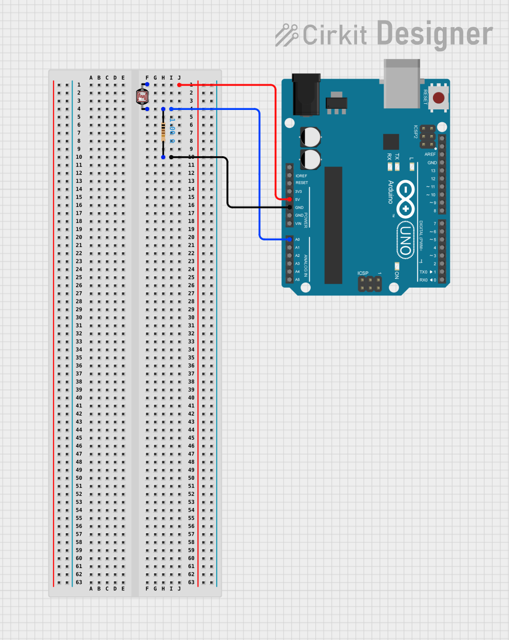
Example Circuit with Arduino UNO

// Photodiode connected to A0 with a 10kΩ load resistor
const int photodiodePin = A0;

void setup() {
  Serial.begin(9600);
}

void loop() {
  int sensorValue = analogRead(photodiodePin); // Read the photodiode
  float voltage = sensorValue * (5.0 / 1023.0); // Convert to voltage
  Serial.println(voltage); // Print the voltage
  delay(200); // Delay for readability
}

Troubleshooting and FAQs

Common Issues

  • Low Responsivity: Ensure that the photodiode is not in a saturated state and that it is properly biased.
  • Noise in Signal: Check for proper filtering and shielding. Ensure that the load resistor value is appropriate.
  • Inconsistent Readings: Verify that the photodiode is not affected by stray light or temperature variations.

Solutions and Tips

  • Shielding: Use opaque materials to shield the photodiode from unwanted light.
  • Filtering: Increase the capacitor value in parallel with the load resistor to reduce high-frequency noise.
  • Temperature Control: Operate the photodiode in a temperature-controlled environment if precise measurements are required.

FAQs

Q: Can I use a photodiode to measure the intensity of laser light? A: Yes, but ensure that the photodiode's spectral response matches the wavelength of the laser and that the intensity does not exceed the maximum rating.

Q: How do I increase the sensitivity of my photodiode circuit? A: Use a transimpedance amplifier with a higher feedback resistor value to increase gain, but be mindful of bandwidth and noise implications.

Q: What is the difference between a photodiode and a phototransistor? A: A phototransistor is similar to a photodiode but with internal gain. It is generally more sensitive but slower than a photodiode.

Remember to always consult the specific datasheet of the photodiode model you are using for precise specifications and recommendations.