How to Use rasp4b-pins: Examples, Pinouts, and Specs
Introduction
The Rasp4B-Pins are the GPIO (General Purpose Input/Output) pins on the Raspberry Pi 4 Model B, manufactured by Rasp. These pins are designed to interface with a wide range of electronic components, sensors, and modules, enabling users to create custom hardware projects. The GPIO pins support digital input and output, as well as specialized functions such as I2C, SPI, UART, and PWM.
Explore Projects Built with rasp4b-pins

Explore Projects Built with rasp4b-pins
Common Applications and Use Cases
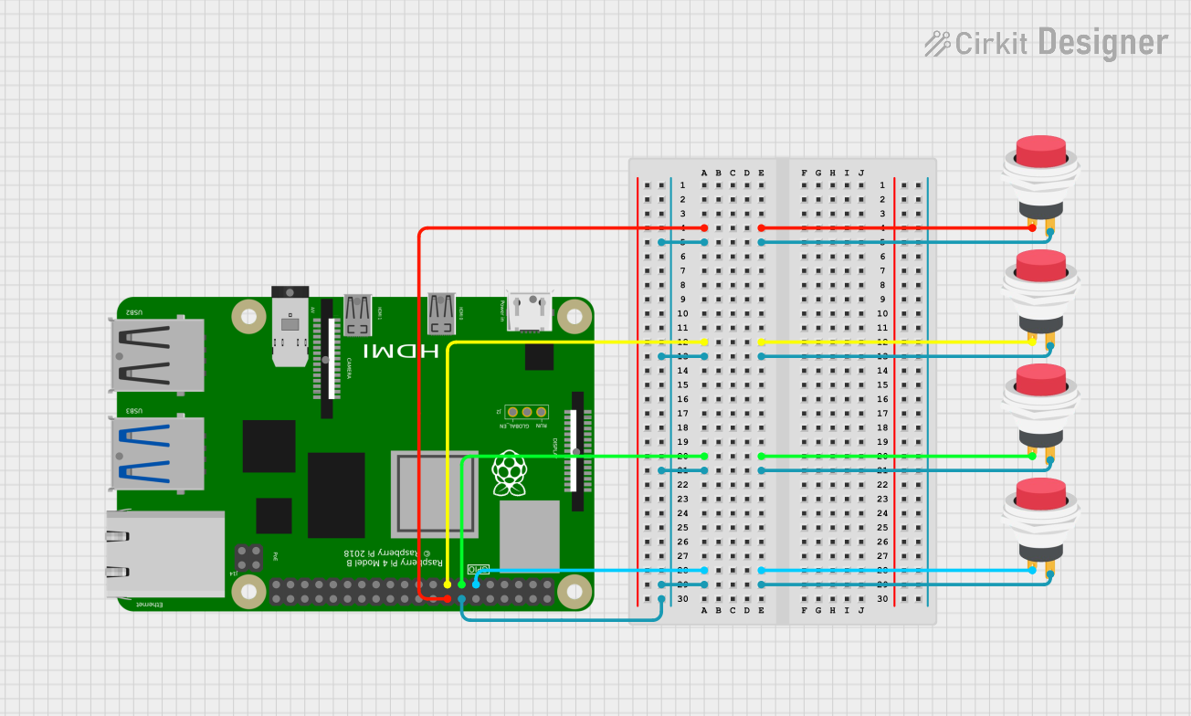
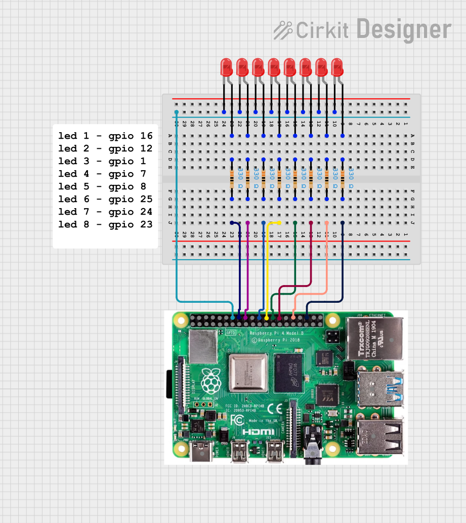
- Controlling LEDs, motors, and relays
- Reading data from sensors (e.g., temperature, humidity, motion)
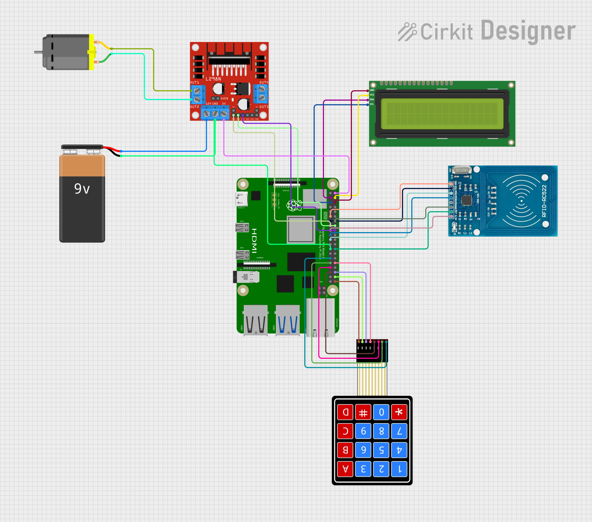
- Communicating with other devices via I2C, SPI, or UART protocols
- Building IoT (Internet of Things) devices
- Prototyping embedded systems and robotics projects
Technical Specifications
The GPIO pins on the Raspberry Pi 4 Model B are arranged in a 40-pin header. Below are the key technical details and pin configuration:
Key Technical Details
- Voltage Levels: 3.3V logic (do not exceed 3.3V on input pins)
- Maximum Current per Pin: 16 mA
- Total Maximum Current: 50 mA (shared across all GPIO pins)
- Communication Protocols Supported: I2C, SPI, UART, PWM
- Power Pins: 5V and 3.3V power output available
- Ground Pins: Multiple GND pins for circuit grounding
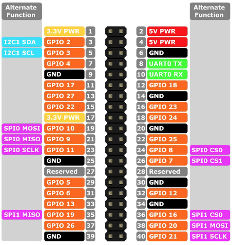
Pin Configuration and Descriptions
The GPIO header consists of 40 pins arranged in two rows of 20 pins each. Below is the pinout table:
| Pin Number | Pin Name | Function/Description |
|---|---|---|
| 1 | 3.3V Power | 3.3V power output |
| 2 | 5V Power | 5V power output |
| 3 | GPIO2 (SDA1) | I2C Data (SDA) |
| 4 | 5V Power | 5V power output |
| 5 | GPIO3 (SCL1) | I2C Clock (SCL) |
| 6 | GND | Ground |
| 7 | GPIO4 | General Purpose I/O |
| 8 | GPIO14 (TXD0) | UART Transmit (TX) |
| 9 | GND | Ground |
| 10 | GPIO15 (RXD0) | UART Receive (RX) |
| 11 | GPIO17 | General Purpose I/O |
| 12 | GPIO18 (PWM0) | PWM Output |
| 13 | GPIO27 | General Purpose I/O |
| 14 | GND | Ground |
| 15 | GPIO22 | General Purpose I/O |
| 16 | GPIO23 | General Purpose I/O |
| 17 | 3.3V Power | 3.3V power output |
| 18 | GPIO24 | General Purpose I/O |
| 19 | GPIO10 (MOSI) | SPI Master Out Slave In (MOSI) |
| 20 | GND | Ground |
| 21 | GPIO9 (MISO) | SPI Master In Slave Out (MISO) |
| 22 | GPIO25 | General Purpose I/O |
| 23 | GPIO11 (SCLK) | SPI Clock (SCLK) |
| 24 | GPIO8 (CE0) | SPI Chip Enable 0 (CE0) |
| 25 | GND | Ground |
| 26 | GPIO7 (CE1) | SPI Chip Enable 1 (CE1) |
| 27 | GPIO0 (ID_SD) | I2C ID EEPROM Data |
| 28 | GPIO1 (ID_SC) | I2C ID EEPROM Clock |
| 29 | GPIO5 | General Purpose I/O |
| 30 | GND | Ground |
| 31 | GPIO6 | General Purpose I/O |
| 32 | GPIO12 (PWM0) | PWM Output |
| 33 | GPIO13 (PWM1) | PWM Output |
| 34 | GND | Ground |
| 35 | GPIO19 (PCM_FS) | PCM Frame Sync |
| 36 | GPIO16 | General Purpose I/O |
| 37 | GPIO26 | General Purpose I/O |
| 38 | GPIO20 (PCM_DIN) | PCM Data In |
| 39 | GND | Ground |
| 40 | GPIO21 (PCM_DOUT) | PCM Data Out |
Usage Instructions
How to Use the Component in a Circuit
- Powering the GPIO Pins: Use the 3.3V or 5V power pins to supply power to external components. Ensure the total current draw does not exceed the Raspberry Pi's limits.
- Connecting Sensors and Actuators: Use the GPIO pins to interface with sensors (e.g., temperature, motion) or actuators (e.g., LEDs, motors). Use appropriate resistors or transistors to protect the GPIO pins.
- Using Communication Protocols:
- For I2C devices, connect SDA to GPIO2 and SCL to GPIO3.
- For SPI devices, use GPIO10 (MOSI), GPIO9 (MISO), GPIO11 (SCLK), and GPIO8/GPIO7 (CE).
- For UART communication, use GPIO14 (TX) and GPIO15 (RX).
Important Considerations and Best Practices
- Voltage Levels: The GPIO pins operate at 3.3V logic. Applying 5V directly to a GPIO pin can damage the Raspberry Pi.
- Current Limits: Do not exceed 16 mA per pin or 50 mA total across all GPIO pins.
- Use Pull-Up/Pull-Down Resistors: Configure GPIO pins with pull-up or pull-down resistors as needed to avoid floating inputs.
- Protective Circuits: Use diodes, resistors, or level shifters to protect the GPIO pins when interfacing with higher voltage devices.
Example: Blinking an LED with Arduino UNO
Below is an example of how to control an LED connected to a GPIO pin using Python and the Raspberry Pi's GPIO library:
Import the GPIO library
import RPi.GPIO as GPIO import time
Set the GPIO mode to BCM (Broadcom pin numbering)
GPIO.setmode(GPIO.BCM)
Define the GPIO pin connected to the LED
LED_PIN = 17
Set the LED pin as an output
GPIO.setup(LED_PIN, GPIO.OUT)
try: while True: GPIO.output(LED_PIN, GPIO.HIGH) # Turn the LED on time.sleep(1) # Wait for 1 second GPIO.output(LED_PIN, GPIO.LOW) # Turn the LED off time.sleep(1) # Wait for 1 second except KeyboardInterrupt: # Clean up GPIO settings on exit GPIO.cleanup()
Troubleshooting and FAQs
Common Issues Users Might Face
GPIO Pin Not Responding:
- Cause: Incorrect pin numbering or configuration.
- Solution: Double-check the pin numbering (BCM vs. BOARD) and ensure the pin is configured correctly (input/output).
Overheating or Damage to GPIO Pins:
- Cause: Exceeding voltage or current limits.
- Solution: Ensure the voltage does not exceed 3.3V and the current is within safe limits.
I2C or SPI Devices Not Communicating:
- Cause: Incorrect wiring or missing software configuration.
- Solution: Verify the connections and enable I2C/SPI in the Raspberry Pi configuration settings.
Floating GPIO Pins:
- Cause: Unused GPIO pins left unconnected.
- Solution: Use pull-up or pull-down resistors to stabilize unused pins.
Solutions and Tips for Troubleshooting
- Use a multimeter to check voltage levels and continuity in your circuit.
- Refer to the Raspberry Pi documentation for additional details on GPIO pin functions.
- Test your circuit with a simple script to isolate issues before adding complexity.