Cirkit Designer Logo
Cirkit Designer
Your all-in-one circuit design IDE
Home / 
Component Documentation

How to Use Current Sensor ACS712 : Examples, Pinouts, and Specs

Image of Current Sensor ACS712
Cirkit Designer LogoDesign with Current Sensor ACS712 in Cirkit Designer

Introduction

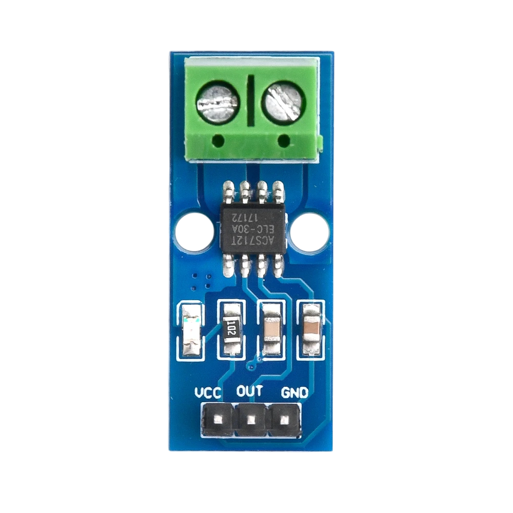
The ACS712 is a Hall effect-based current sensor that provides an analog output proportional to the current flowing through it. It is capable of measuring both AC and DC currents, making it a versatile component for a wide range of applications. The sensor is available in different variants to measure currents up to ±5A, ±20A, or ±30A. Its compact design and ease of use make it a popular choice for current monitoring and control in electrical systems.

Explore Projects Built with Current Sensor ACS712

Use Cirkit Designer to design, explore, and prototype these projects online. Some projects support real-time simulation. Click "Open Project" to start designing instantly!
Wemos S2 Mini Controlled Smart Device with OLED Display, Thermal Printing, and RGB LED Strip
Image of DT NEA - Noah Patel: A project utilizing Current Sensor ACS712  in a practical application
This circuit features a Wemos S2 Mini microcontroller that controls a WS2812 RGB LED strip and communicates with a 0.96" OLED display and a 58mm mini thermal printer. The ACS712 Current Sensor is interfaced with the microcontroller to monitor current, and power is managed by a CD42 BMS connected to two 18650 Li-ion batteries, with a USB-C PD Trigger Board for power delivery. The circuit is designed for visual output (LED strip, OLED display), printing capabilities, and current sensing, likely for a portable, battery-powered monitoring and display device.
Cirkit Designer LogoOpen Project in Cirkit Designer
ESP32-Based Current Monitoring and Temperature Sensing System
Image of SISTEMA DE MONITOREO: A project utilizing Current Sensor ACS712  in a practical application
This circuit is designed to measure current using an ACS712 Current Sensor and temperature using a DS18B20 sensor, with an ESP32 microcontroller to process and possibly communicate the sensor data. The ACS712 sensor output is connected to one of the ESP32's analog input pins (D34), while the DS18B20's signal line is interfaced with a digital input pin (D23) through a pull-up resistor (4.7k Ohms). The ESP32 is powered through its Vin pin, and both sensors share a common ground with the ESP32.
Cirkit Designer LogoOpen Project in Cirkit Designer
ESP32-Controlled Smart Lighting System with Power Monitoring
Image of Energy Monitoring System: A project utilizing Current Sensor ACS712  in a practical application
This circuit appears to be a multi-channel current monitoring system using several ACS712 current sensors to measure the current through different loads, likely bulbs connected to a 220V power source. The current readings from the sensors are digitized by an Adafruit ADS1115 16-bit ADC, which interfaces with an ESP32 microcontroller via I2C communication for further processing or telemetry. A buck converter is used to step down the voltage to power the ESP32 and the sensors, and the system is powered through a 2.1mm DC barrel jack, indicating it is designed for external power supply.
Cirkit Designer LogoOpen Project in Cirkit Designer
Arduino and GSM-Based Power Monitoring and Wi-Fi Controlled Lighting System
Image of light monitoring system: A project utilizing Current Sensor ACS712  in a practical application
This circuit is designed to monitor voltage and current using ACS712 current sensors and voltage sensors, calculate power, and control lighting via relay modules. It features an Arduino Uno R3 for processing sensor data and executing control logic, which includes sending alerts via a GSM module (sim 800l) if power falls below a threshold and connecting to WiFi using an ESP8266 module. The circuit also includes a battery with a charging module (TP4056), a step-up boost converter, and multiple AC power supplies with circuit breakers for safety.
Cirkit Designer LogoOpen Project in Cirkit Designer

Explore Projects Built with Current Sensor ACS712

Use Cirkit Designer to design, explore, and prototype these projects online. Some projects support real-time simulation. Click "Open Project" to start designing instantly!
Image of DT NEA - Noah Patel: A project utilizing Current Sensor ACS712  in a practical application
Wemos S2 Mini Controlled Smart Device with OLED Display, Thermal Printing, and RGB LED Strip
This circuit features a Wemos S2 Mini microcontroller that controls a WS2812 RGB LED strip and communicates with a 0.96" OLED display and a 58mm mini thermal printer. The ACS712 Current Sensor is interfaced with the microcontroller to monitor current, and power is managed by a CD42 BMS connected to two 18650 Li-ion batteries, with a USB-C PD Trigger Board for power delivery. The circuit is designed for visual output (LED strip, OLED display), printing capabilities, and current sensing, likely for a portable, battery-powered monitoring and display device.
Cirkit Designer LogoOpen Project in Cirkit Designer
Image of SISTEMA DE MONITOREO: A project utilizing Current Sensor ACS712  in a practical application
ESP32-Based Current Monitoring and Temperature Sensing System
This circuit is designed to measure current using an ACS712 Current Sensor and temperature using a DS18B20 sensor, with an ESP32 microcontroller to process and possibly communicate the sensor data. The ACS712 sensor output is connected to one of the ESP32's analog input pins (D34), while the DS18B20's signal line is interfaced with a digital input pin (D23) through a pull-up resistor (4.7k Ohms). The ESP32 is powered through its Vin pin, and both sensors share a common ground with the ESP32.
Cirkit Designer LogoOpen Project in Cirkit Designer
Image of Energy Monitoring System: A project utilizing Current Sensor ACS712  in a practical application
ESP32-Controlled Smart Lighting System with Power Monitoring
This circuit appears to be a multi-channel current monitoring system using several ACS712 current sensors to measure the current through different loads, likely bulbs connected to a 220V power source. The current readings from the sensors are digitized by an Adafruit ADS1115 16-bit ADC, which interfaces with an ESP32 microcontroller via I2C communication for further processing or telemetry. A buck converter is used to step down the voltage to power the ESP32 and the sensors, and the system is powered through a 2.1mm DC barrel jack, indicating it is designed for external power supply.
Cirkit Designer LogoOpen Project in Cirkit Designer
Image of light monitoring system: A project utilizing Current Sensor ACS712  in a practical application
Arduino and GSM-Based Power Monitoring and Wi-Fi Controlled Lighting System
This circuit is designed to monitor voltage and current using ACS712 current sensors and voltage sensors, calculate power, and control lighting via relay modules. It features an Arduino Uno R3 for processing sensor data and executing control logic, which includes sending alerts via a GSM module (sim 800l) if power falls below a threshold and connecting to WiFi using an ESP8266 module. The circuit also includes a battery with a charging module (TP4056), a step-up boost converter, and multiple AC power supplies with circuit breakers for safety.
Cirkit Designer LogoOpen Project in Cirkit Designer

Common Applications

  • Power monitoring in household and industrial devices
  • Overcurrent protection in circuits
  • Battery management systems
  • Motor control and monitoring
  • Energy metering and load detection

Technical Specifications

Below are the key technical details of the ACS712 current sensor:

Parameter Value
Supply Voltage (Vcc) 4.5V to 5.5V
Measurement Range ±5A, ±20A, or ±30A (depending on model)
Sensitivity (Typ.) 185mV/A (±5A), 100mV/A (±20A), 66mV/A (±30A)
Output Voltage Analog, centered at Vcc/2
Response Time 5 µs
Bandwidth 80 kHz
Operating Temperature -40°C to 85°C
Package Type SOIC-8

Pin Configuration and Descriptions

The ACS712 has 8 pins, but only a few are typically used in most applications. Below is the pinout:

Pin Number Pin Name Description
1, 2, 3 IP+ Current input terminal (positive side of load)
4, 5, 6 IP- Current input terminal (negative side of load)
7 Vcc Power supply (4.5V to 5.5V)
8 OUT Analog voltage output proportional to current

Usage Instructions

How to Use the ACS712 in a Circuit

  1. Power the Sensor: Connect the Vcc pin to a 5V power supply and the GND pin to the ground of your circuit.
  2. Connect the Load: Pass the current-carrying wire through the IP+ and IP- terminals. Ensure the current flows in the correct direction as indicated on the sensor.
  3. Read the Output: The OUT pin provides an analog voltage proportional to the current. At 0A, the output voltage is approximately Vcc/2 (2.5V for a 5V supply). The voltage increases or decreases based on the current direction.

Important Considerations

  • Calibration: The sensor's output may vary slightly due to manufacturing tolerances. Calibrate the sensor in your application for accurate readings.
  • Noise Filtering: Add a capacitor (e.g., 0.1 µF) between the OUT pin and GND to reduce noise in the output signal.
  • Current Range: Ensure you select the correct ACS712 variant (±5A, ±20A, or ±30A) based on your application's current range.
  • Isolation: The ACS712 provides electrical isolation between the current-carrying conductor and the sensor's output, enhancing safety.

Example: Using ACS712 with Arduino UNO

Below is an example of how to interface the ACS712 with an Arduino UNO to measure current:

// Include necessary libraries (if any)

// Define the analog pin connected to the ACS712 OUT pin
const int sensorPin = A0;

// Define the sensitivity of the ACS712 (e.g., 185mV/A for ±5A model)
const float sensitivity = 0.185; // Sensitivity in V/A

// Define the supply voltage (Vcc) of the sensor
const float Vcc = 5.0; // Supply voltage in volts

// Define the zero-current voltage (Vcc/2)
const float zeroCurrentVoltage = Vcc / 2;

void setup() {
  Serial.begin(9600); // Initialize serial communication
}

void loop() {
  // Read the analog value from the sensor
  int sensorValue = analogRead(sensorPin);

  // Convert the analog value to voltage
  float sensorVoltage = (sensorValue / 1023.0) * Vcc;

  // Calculate the current in amperes
  float current = (sensorVoltage - zeroCurrentVoltage) / sensitivity;

  // Print the current value to the Serial Monitor
  Serial.print("Current: ");
  Serial.print(current);
  Serial.println(" A");

  delay(1000); // Wait for 1 second before the next reading
}

Notes:

  • Replace sensitivity with the appropriate value for your ACS712 variant (e.g., 0.1 for ±20A, 0.066 for ±30A).
  • Ensure the current-carrying wire is properly connected to the IP+ and IP- terminals.

Troubleshooting and FAQs

Common Issues and Solutions

  1. No Output or Incorrect Readings

    • Cause: Incorrect wiring or loose connections.
    • Solution: Double-check all connections, especially the Vcc, GND, and OUT pins.
  2. High Noise in Output

    • Cause: Electrical noise or lack of filtering.
    • Solution: Add a 0.1 µF capacitor between the OUT pin and GND to filter noise.
  3. Output Voltage Does Not Change

    • Cause: Current is not flowing through the IP+ and IP- terminals.
    • Solution: Ensure the current-carrying wire is properly connected and the load is active.
  4. Inaccurate Current Measurements

    • Cause: Sensor not calibrated or incorrect sensitivity value used.
    • Solution: Calibrate the sensor by measuring a known current and adjusting calculations accordingly.

FAQs

Q: Can the ACS712 measure both AC and DC currents?
A: Yes, the ACS712 can measure both AC and DC currents. The output voltage will vary proportionally with the instantaneous current.

Q: How do I select the correct ACS712 variant?
A: Choose the variant based on the maximum current you need to measure. For example, use the ±5A model for small currents and the ±30A model for larger currents.

Q: Is the ACS712 safe to use with high voltages?
A: Yes, the ACS712 provides electrical isolation between the current-carrying conductor and the sensor's output, making it safe for high-voltage applications.

Q: Can I use the ACS712 with a 3.3V microcontroller?
A: While the ACS712 is designed for a 5V supply, it may work with a 3.3V microcontroller if the output voltage range is within the ADC input range. However, accuracy may be affected.