Cirkit Designer Logo
Cirkit Designer
Your all-in-one circuit design IDE
Home / 
Component Documentation

How to Use PN532: Examples, Pinouts, and Specs

Image of PN532
Cirkit Designer LogoDesign with PN532 in Cirkit Designer

Introduction

The PN532 is a versatile NFC (Near Field Communication) controller that enables seamless communication with NFC-enabled devices. It supports multiple modes of operation, including reader/writer, peer-to-peer, and card emulation. This makes it a popular choice for a wide range of applications such as contactless payments, access control, and data exchange. Its robust design and compatibility with various communication protocols (I2C, SPI, and UART) make it a go-to solution for NFC-based projects.

Explore Projects Built with PN532

Use Cirkit Designer to design, explore, and prototype these projects online. Some projects support real-time simulation. Click "Open Project" to start designing instantly!
Arduino Mega 2560 Based Security System with Fingerprint Authentication and SMS Alerts
Image of Door security system: A project utilizing PN532 in a practical application
This circuit features an Arduino Mega 2560 microcontroller interfaced with a SIM800L GSM module, two fingerprint scanners, an I2C LCD display, an IR sensor, and a piezo buzzer. Power management is handled by a PowerBoost 1000 Basic Pad USB, a TP4056 charging module, and a Li-ion 18650 battery, with an option to use a Mini AC-DC 110V-230V to 5V 700mA module for direct power supply. The primary functionality appears to be a security system with GSM communication capabilities, biometric access control, and visual/audible feedback.
Cirkit Designer LogoOpen Project in Cirkit Designer
Biometric Access Control System with RFID and Touch Activation
Image of DOORLOCK1: A project utilizing PN532 in a practical application
This circuit is designed for security and identification purposes, featuring an RFID-RC522 module for contactless communication and a fingerprint scanner for biometric authentication. It includes an LCD display for user interaction, a touch sensor for input, a buzzer for audio feedback, and a relay module for controlling external devices. The components are interfaced with a NANO Expansion board, which likely contains a microcontroller to coordinate the operations of the system.
Cirkit Designer LogoOpen Project in Cirkit Designer
NFC-Enabled Access Control System with Time Logging
Image of doorlock: A project utilizing PN532 in a practical application
This circuit is designed for access control with time tracking capabilities. It features an NFC/RFID reader for authentication, an RTC module (DS3231) for real-time clock functionality, and an OLED display for user interaction. A 12V relay controls a magnetic lock, which is activated upon successful NFC/RFID authentication, and a button switch is likely used for manual operation or input. The T8_S3 microcontroller serves as the central processing unit, interfacing with the NFC/RFID reader, RTC, OLED, and relay to manage the access control logic.
Cirkit Designer LogoOpen Project in Cirkit Designer
NFC-Enabled Access Control System with Real-Time Clock and OLED Display
Image of doorlock: A project utilizing PN532 in a practical application
This circuit is designed as an access control system with time-tracking capabilities. It uses an NFC/RFID reader for authentication, a real-time clock for time-stamping events, and an OLED display for user interface, all controlled by a T8_S3 microcontroller. A relay module actuates a magnetic lock, and a button switch provides additional user input, with a switching power supply delivering the necessary voltages.
Cirkit Designer LogoOpen Project in Cirkit Designer

Explore Projects Built with PN532

Use Cirkit Designer to design, explore, and prototype these projects online. Some projects support real-time simulation. Click "Open Project" to start designing instantly!
Image of Door security system: A project utilizing PN532 in a practical application
Arduino Mega 2560 Based Security System with Fingerprint Authentication and SMS Alerts
This circuit features an Arduino Mega 2560 microcontroller interfaced with a SIM800L GSM module, two fingerprint scanners, an I2C LCD display, an IR sensor, and a piezo buzzer. Power management is handled by a PowerBoost 1000 Basic Pad USB, a TP4056 charging module, and a Li-ion 18650 battery, with an option to use a Mini AC-DC 110V-230V to 5V 700mA module for direct power supply. The primary functionality appears to be a security system with GSM communication capabilities, biometric access control, and visual/audible feedback.
Cirkit Designer LogoOpen Project in Cirkit Designer
Image of DOORLOCK1: A project utilizing PN532 in a practical application
Biometric Access Control System with RFID and Touch Activation
This circuit is designed for security and identification purposes, featuring an RFID-RC522 module for contactless communication and a fingerprint scanner for biometric authentication. It includes an LCD display for user interaction, a touch sensor for input, a buzzer for audio feedback, and a relay module for controlling external devices. The components are interfaced with a NANO Expansion board, which likely contains a microcontroller to coordinate the operations of the system.
Cirkit Designer LogoOpen Project in Cirkit Designer
Image of doorlock: A project utilizing PN532 in a practical application
NFC-Enabled Access Control System with Time Logging
This circuit is designed for access control with time tracking capabilities. It features an NFC/RFID reader for authentication, an RTC module (DS3231) for real-time clock functionality, and an OLED display for user interaction. A 12V relay controls a magnetic lock, which is activated upon successful NFC/RFID authentication, and a button switch is likely used for manual operation or input. The T8_S3 microcontroller serves as the central processing unit, interfacing with the NFC/RFID reader, RTC, OLED, and relay to manage the access control logic.
Cirkit Designer LogoOpen Project in Cirkit Designer
Image of doorlock: A project utilizing PN532 in a practical application
NFC-Enabled Access Control System with Real-Time Clock and OLED Display
This circuit is designed as an access control system with time-tracking capabilities. It uses an NFC/RFID reader for authentication, a real-time clock for time-stamping events, and an OLED display for user interface, all controlled by a T8_S3 microcontroller. A relay module actuates a magnetic lock, and a button switch provides additional user input, with a switching power supply delivering the necessary voltages.
Cirkit Designer LogoOpen Project in Cirkit Designer

Common Applications and Use Cases

  • Contactless payment systems
  • Access control and authentication
  • Data exchange between NFC-enabled devices
  • Smart posters and NFC tags
  • IoT applications requiring short-range communication

Technical Specifications

The PN532 is a highly capable NFC controller with the following key specifications:

Parameter Value
Operating Voltage 2.7V to 5.5V
Communication Interfaces I2C, SPI, UART
Operating Frequency 13.56 MHz
Maximum Communication Range Up to 5 cm (depending on antenna design)
Current Consumption ~50 mA (active mode), ~100 µA (low-power mode)
Supported NFC Modes Reader/Writer, Peer-to-Peer, Card Emulation
Supported Protocols ISO/IEC 14443A/B, FeliCa, NFC Forum Type 1-4
Operating Temperature -25°C to +85°C

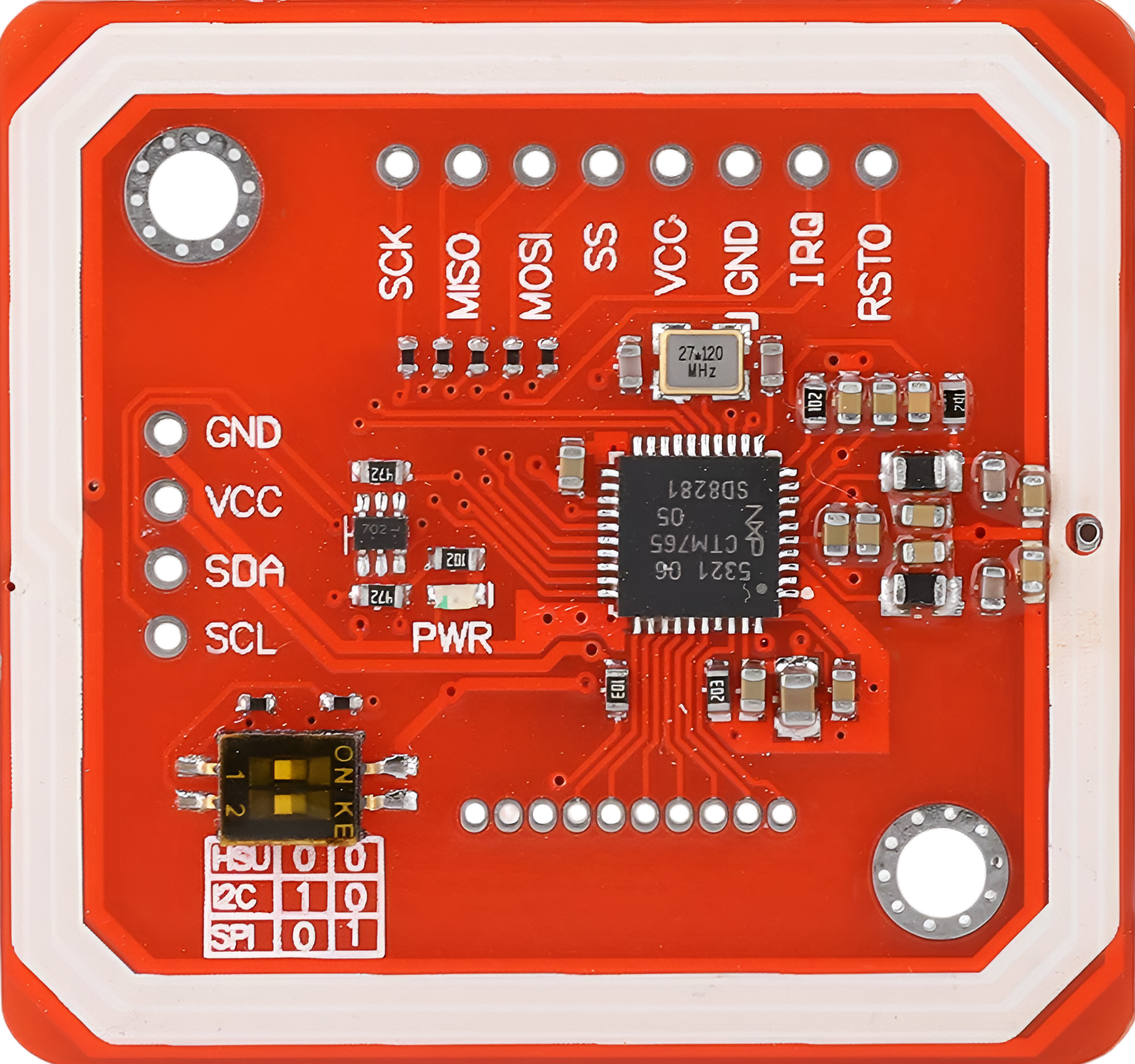
Pin Configuration and Descriptions

The PN532 module typically comes with the following pin configuration:

Pin Name Description
VCC Power supply input (2.7V to 5.5V)
GND Ground connection
SCL I2C clock line (used in I2C mode)
SDA I2C data line (used in I2C mode)
MOSI Master Out Slave In (used in SPI mode)
MISO Master In Slave Out (used in SPI mode)
SCK Serial Clock (used in SPI mode)
NSS SPI chip select (used in SPI mode)
RX UART receive line (used in UART mode)
TX UART transmit line (used in UART mode)
IRQ Interrupt request output
RST Reset pin

Usage Instructions

The PN532 can be used in various modes depending on the application. Below are general steps and considerations for using the PN532 in a circuit:

Connecting the PN532 to an Arduino UNO (I2C Mode)

  1. Wiring: Connect the PN532 module to the Arduino UNO as follows:
    • VCC → 5V (Arduino)
    • GND → GND (Arduino)
    • SDA → A4 (Arduino I2C data line)
    • SCL → A5 (Arduino I2C clock line)
  2. Install Libraries: Use the Adafruit PN532 library for Arduino. Install it via the Arduino Library Manager.
  3. Upload Code: Use the example code below to test the PN532 in I2C mode.

Example Code for Reading NFC Tags

#include <Wire.h>
#include <Adafruit_PN532.h>

// Define the I2C pins for the PN532
#define SDA_PIN A4
#define SCL_PIN A5

// Create an instance of the Adafruit_PN532 class
Adafruit_PN532 nfc(SDA_PIN, SCL_PIN);

void setup() {
  Serial.begin(115200);
  Serial.println("Initializing PN532...");

  // Initialize the PN532
  nfc.begin();

  // Check if the PN532 is connected
  uint32_t versiondata = nfc.getFirmwareVersion();
  if (!versiondata) {
    Serial.println("Didn't find PN532 board");
    while (1); // Halt execution if the board is not found
  }

  // Display firmware version
  Serial.print("Found PN532 with firmware version: ");
  Serial.print((versiondata >> 16) & 0xFF, HEX);
  Serial.print('.');
  Serial.println((versiondata >> 8) & 0xFF, HEX);

  // Configure the board to read NFC tags
  nfc.SAMConfig();
  Serial.println("Waiting for an NFC tag...");
}

void loop() {
  uint8_t success;
  uint8_t uid[] = { 0 }; // Buffer to store the UID
  uint8_t uidLength;

  // Try to read an NFC tag
  success = nfc.readPassiveTargetID(PN532_MIFARE_ISO14443A, uid, &uidLength);

  if (success) {
    Serial.println("NFC tag detected!");
    Serial.print("UID Length: "); Serial.print(uidLength, DEC); Serial.println(" bytes");
    Serial.print("UID Value: ");
    for (uint8_t i = 0; i < uidLength; i++) {
      Serial.print(" 0x"); Serial.print(uid[i], HEX);
    }
    Serial.println();
    delay(1000); // Wait before scanning again
  }
}

Important Considerations and Best Practices

  • Power Supply: Ensure the PN532 module is powered within its operating voltage range (2.7V to 5.5V).
  • Antenna Placement: For optimal performance, avoid placing the antenna near metal objects or other sources of interference.
  • Communication Mode: Configure the module for the desired communication mode (I2C, SPI, or UART) using the appropriate jumpers or settings on the module.
  • Library Compatibility: Use a reliable library, such as the Adafruit PN532 library, to simplify communication with the module.

Troubleshooting and FAQs

Common Issues and Solutions

  1. PN532 Not Detected

    • Cause: Incorrect wiring or communication mode.
    • Solution: Double-check the wiring and ensure the module is configured for the correct communication mode (e.g., I2C, SPI, or UART).
  2. NFC Tags Not Detected

    • Cause: Antenna placement or unsupported tag type.
    • Solution: Ensure the tag is within range (up to 5 cm) and is of a supported type (e.g., ISO/IEC 14443A/B).
  3. Intermittent Communication

    • Cause: Noise or interference in the circuit.
    • Solution: Use shorter wires and ensure proper grounding. Add decoupling capacitors if necessary.
  4. Firmware Version Not Displayed

    • Cause: Faulty module or incorrect initialization.
    • Solution: Verify the module's power supply and reinitialize the PN532 using the library.

FAQs

Q: Can the PN532 read all types of NFC tags?
A: The PN532 supports ISO/IEC 14443A/B, FeliCa, and NFC Forum Type 1-4 tags. Ensure your tag is compatible with these standards.

Q: How do I switch between I2C, SPI, and UART modes?
A: The PN532 module typically has jumpers or solder pads to configure the communication mode. Refer to the module's datasheet for specific instructions.

Q: What is the maximum range of the PN532?
A: The maximum range is approximately 5 cm, depending on the antenna design and environmental factors.

Q: Can the PN532 be used for peer-to-peer communication?
A: Yes, the PN532 supports peer-to-peer mode for data exchange between two NFC-enabled devices.