How to Use Alltrax SR48300 Motor Controller: Examples, Pinouts, and Specs
Introduction
The Alltrax SR48300 is a high-performance motor controller designed for DC motor applications, particularly in electric vehicles (EVs), golf carts, utility vehicles, and industrial equipment. This controller offers advanced features such as programmable speed settings, regenerative braking, and robust thermal management, making it ideal for demanding environments. Its versatility and reliability ensure precise motor control and efficient operation.
Explore Projects Built with Alltrax SR48300 Motor Controller
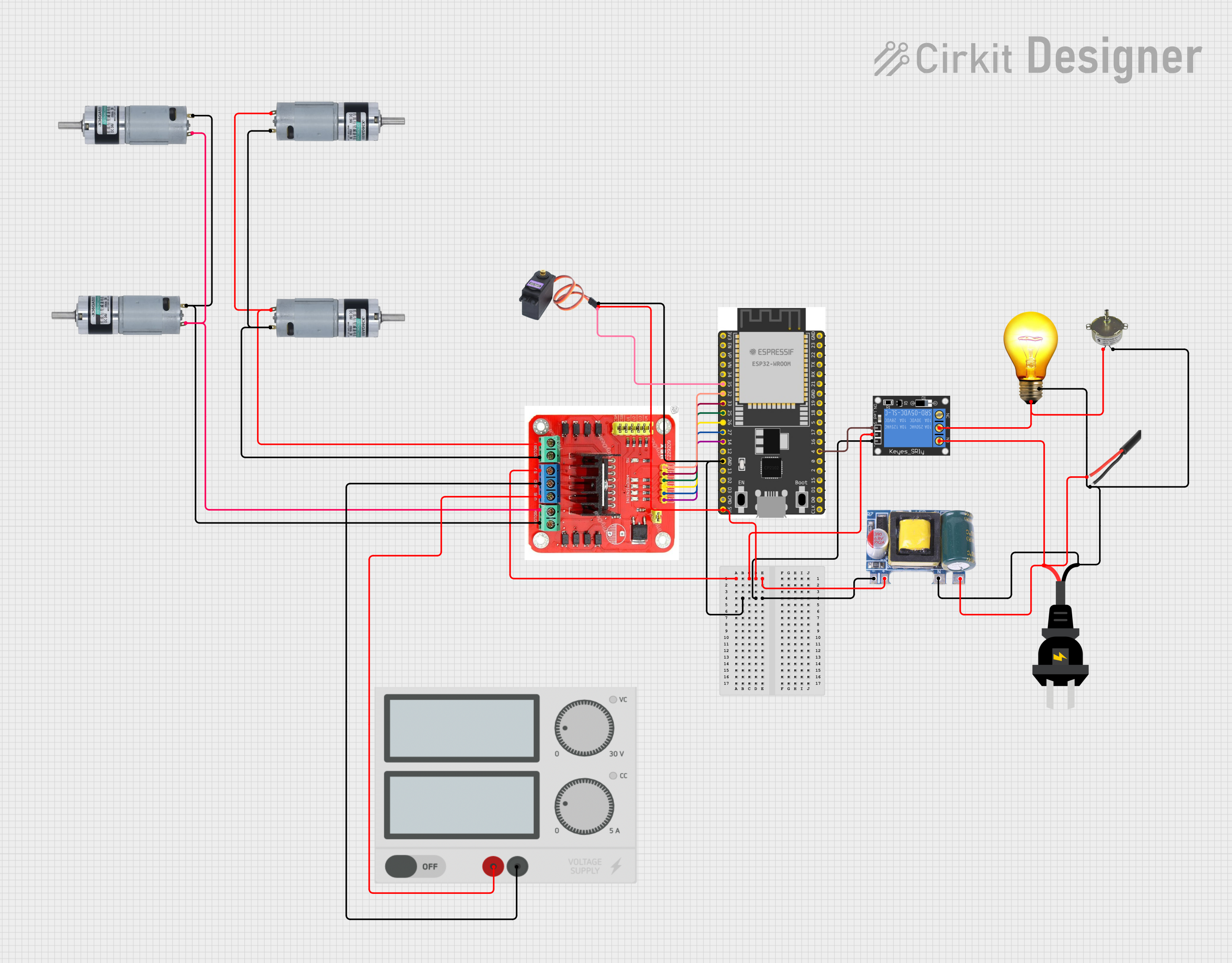

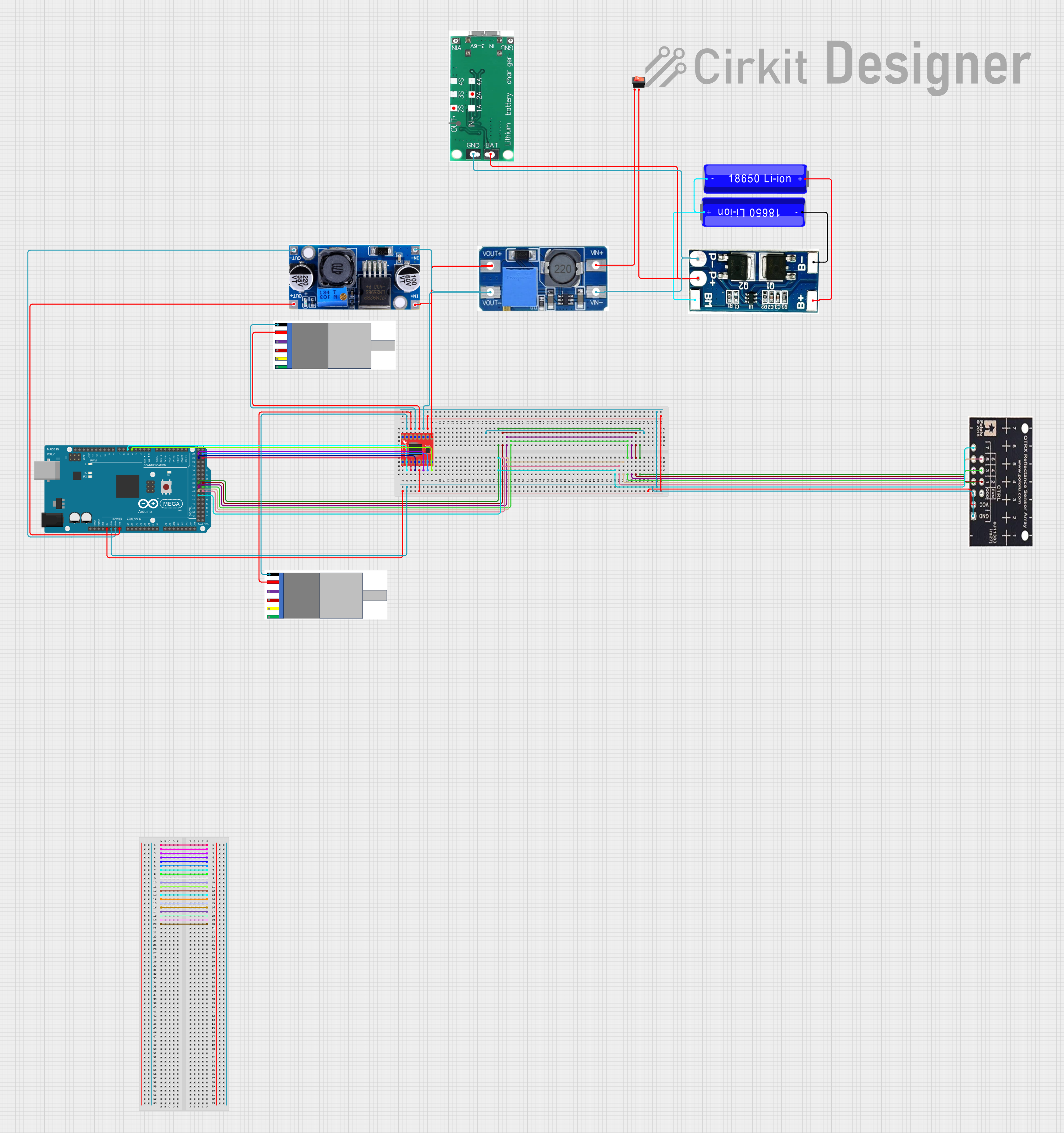
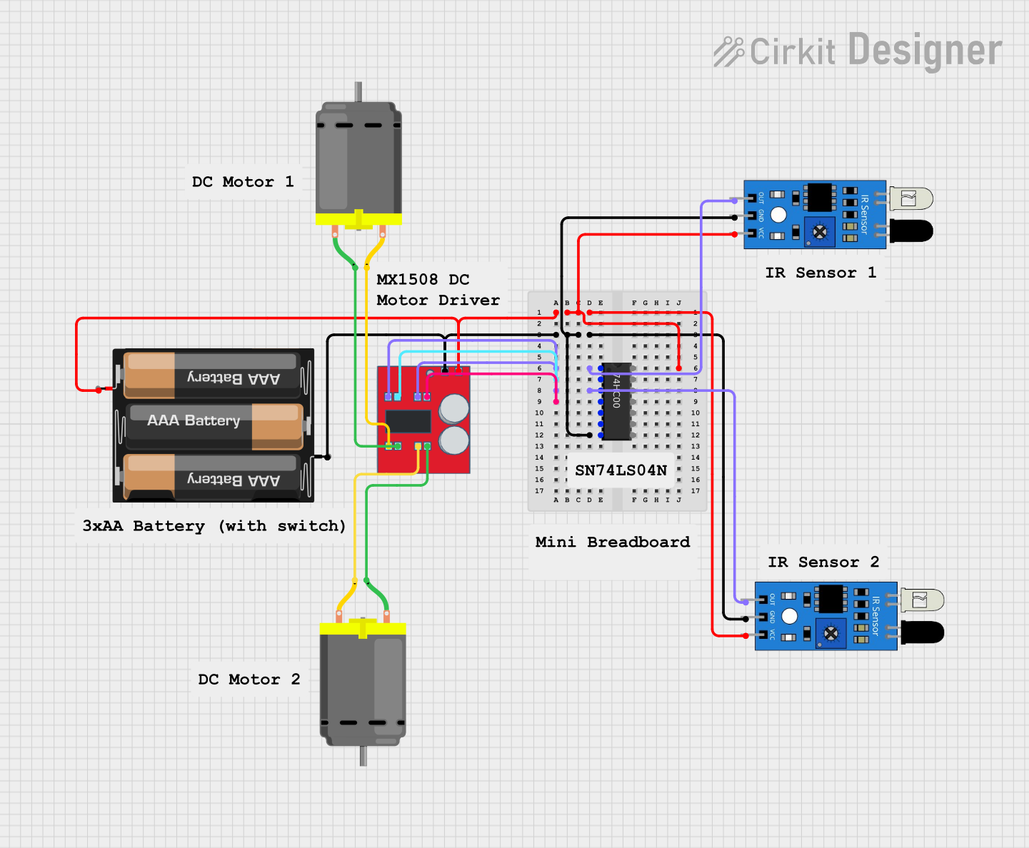
Explore Projects Built with Alltrax SR48300 Motor Controller
Common Applications
- Electric vehicles (e.g., golf carts, utility vehicles, and scooters)
- Industrial machinery and conveyor systems
- Marine applications (e.g., electric boats)
- Renewable energy systems (e.g., wind turbine yaw motors)
- Robotics and automation systems
Technical Specifications
Key Technical Details
| Parameter | Value |
|---|---|
| Manufacturer | Alltrax |
| Part Number | SR48300 |
| Input Voltage Range | 24V - 48V DC |
| Continuous Current Rating | 300A |
| Peak Current Rating | 400A (for 2 minutes) |
| Motor Type Supported | Series-wound DC motors |
| Regenerative Braking | Yes |
| Thermal Protection | Yes (with heatsink and fan) |
| Communication Interface | USB (for programming) |
| Dimensions | 8.3" x 6.5" x 3.1" (L x W x H) |
| Weight | 4.5 lbs (2.04 kg) |
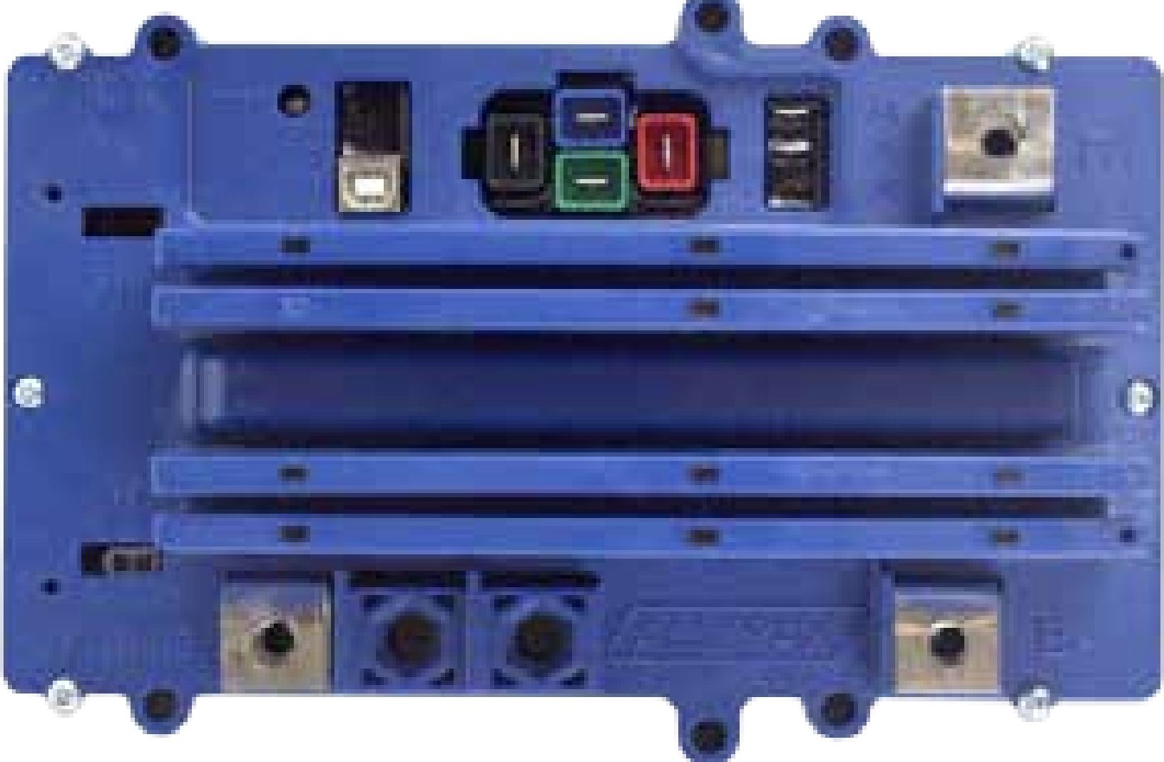
Pin Configuration and Descriptions
The SR48300 motor controller has several key terminals and connectors for power, motor, and control signals. Below is a detailed description:
Power and Motor Terminals
| Terminal Label | Description |
|---|---|
| B+ | Battery positive terminal |
| B- | Battery negative terminal |
| M- | Motor negative terminal |
| A2 | Auxiliary motor terminal (optional) |
Control Signal Terminals
| Terminal Label | Description |
|---|---|
| KSI | Key switch input (activates the controller) |
| F1, F2 | Field terminals for motor field winding |
| Throttle | Throttle input (0-5V or 3-wire potentiometer) |
| USB Port | For programming and diagnostics via PC |
Usage Instructions
How to Use the SR48300 in a Circuit
- Power Connections:
- Connect the battery positive terminal to
B+and the battery negative terminal toB-. - Ensure the battery voltage is within the supported range (24V - 48V DC).
- Connect the battery positive terminal to
- Motor Connections:
- Connect the motor's negative terminal to
M-. - If the motor has an auxiliary terminal, connect it to
A2(optional). - Connect the motor's field winding to
F1andF2.
- Connect the motor's negative terminal to
- Control Connections:
- Connect the throttle input to the
Throttleterminal. Use a compatible 0-5V throttle or a 3-wire potentiometer. - Wire the key switch to the
KSIterminal to enable the controller.
- Connect the throttle input to the
- Programming:
- Use the USB port to connect the controller to a PC.
- Download and install the Alltrax Toolkit software from the manufacturer's website.
- Use the software to configure parameters such as speed limits, acceleration, and regenerative braking.
Important Considerations and Best Practices
- Wiring: Use appropriately rated cables for the current and voltage to prevent overheating or voltage drops.
- Cooling: Ensure proper airflow around the controller's heatsink and fan to avoid thermal shutdown.
- Fusing: Install a fuse or circuit breaker on the battery positive line for safety.
- Programming: Always save a backup of the default configuration before making changes.
- Polarity: Double-check all connections to avoid damage due to reversed polarity.
Example: Connecting to an Arduino UNO
The SR48300 can be controlled via an Arduino UNO for advanced applications such as automated speed control. Below is an example of how to send a throttle signal using PWM:
// Example: Sending a throttle signal to the SR48300 motor controller
// This code generates a PWM signal to control motor speed via the Throttle input.

const int throttlePin = 9; // PWM pin connected to the Throttle terminal

void setup() {
  pinMode(throttlePin, OUTPUT); // Set the throttle pin as an output
}

void loop() {
  // Generate a PWM signal to control motor speed
  // 0% duty cycle (motor off)
  analogWrite(throttlePin, 0);
  delay(2000); // Wait for 2 seconds

  // 50% duty cycle (half speed)
  analogWrite(throttlePin, 128);
  delay(2000); // Wait for 2 seconds

  // 100% duty cycle (full speed)
  analogWrite(throttlePin, 255);
  delay(2000); // Wait for 2 seconds
}
Note: Ensure the Arduino's ground is connected to the SR48300's ground for proper signal reference.
Troubleshooting and FAQs
Common Issues and Solutions
Controller Does Not Power On:
- Check the
KSIconnection and ensure the key switch is turned on. - Verify the battery voltage is within the supported range (24V - 48V DC).
- Inspect the fuse or circuit breaker for faults.
- Check the
Motor Does Not Respond:
- Ensure the throttle input is correctly connected and functioning.
- Verify motor connections (
M-,A2,F1,F2) are secure and correct. - Check the Alltrax Toolkit software for error codes or diagnostic messages.
Overheating:
- Ensure the controller's heatsink and fan are not obstructed.
- Reduce the motor load or improve ventilation around the controller.
Regenerative Braking Not Working:
- Verify that regenerative braking is enabled in the Alltrax Toolkit software.
- Ensure the battery can handle the regenerative current.
FAQs
Can the SR48300 be used with brushless motors? No, the SR48300 is designed specifically for series-wound DC motors.
What is the maximum wire gauge supported? The controller supports wire gauges up to 2 AWG for power connections.
Is the SR48300 waterproof? The controller is not fully waterproof but is designed to be water-resistant. Avoid submerging it in water.
Can I use the SR48300 with a 12V battery? No, the minimum input voltage is 24V DC. Using a 12V battery may damage the controller.
By following this documentation, users can effectively integrate and operate the Alltrax SR48300 motor controller in their applications.