How to Use VL53L1X: Examples, Pinouts, and Specs
Introduction
The VL53L1X is a time-of-flight (ToF) distance sensor developed by Adafruit. It uses laser technology to measure distances with high accuracy and precision. This sensor can measure distances ranging from 4 cm to 4 meters, making it ideal for applications requiring precise distance measurements. The VL53L1X is widely used in robotics, automation, drones, and IoT devices for obstacle detection, ranging, and proximity sensing.
Explore Projects Built with VL53L1X


Explore Projects Built with VL53L1X
Common Applications:
- Obstacle detection in robotics
- Distance measurement in drones
- Proximity sensing in IoT devices
- Gesture recognition systems
- Industrial automation and safety systems
Technical Specifications
The VL53L1X sensor is compact and highly efficient, with the following key specifications:
| Parameter | Value |
|---|---|
| Operating Voltage | 2.6V to 3.5V |
| Communication Interface | I²C |
| Measurement Range | 4 cm to 4 meters |
| Accuracy | ±1 mm |
| Field of View (FoV) | Programmable, up to 27° |
| Operating Temperature | -20°C to +85°C |
| Power Consumption | 20 mW (typical) |
| Dimensions | 4.9 mm x 2.5 mm x 1.56 mm |
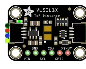
Pin Configuration and Descriptions
The VL53L1X sensor module typically comes with the following pins:
| Pin Name | Description |
|---|---|
| VIN | Power supply input (2.6V to 5V). Connect to the 3.3V or 5V pin of your microcontroller. |
| GND | Ground connection. Connect to the ground of your circuit. |
| SDA | I²C data line. Connect to the SDA pin of your microcontroller. |
| SCL | I²C clock line. Connect to the SCL pin of your microcontroller. |
| XSHUT | Shutdown pin. Pull low to disable the sensor, or leave unconnected for normal operation. |
| GPIO1 | Interrupt pin. Can be used for custom interrupt configurations. |
Usage Instructions
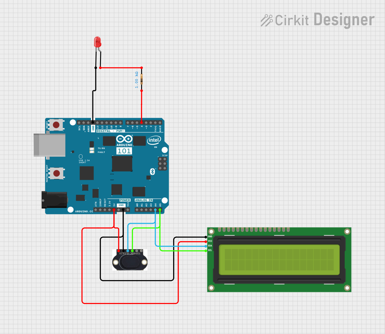
Connecting the VL53L1X to an Arduino UNO
To use the VL53L1X with an Arduino UNO, follow these steps:
- Connect the VIN pin of the VL53L1X to the 5V pin of the Arduino.
- Connect the GND pin of the VL53L1X to the GND pin of the Arduino.
- Connect the SDA pin of the VL53L1X to the A4 pin of the Arduino (I²C data line).
- Connect the SCL pin of the VL53L1X to the A5 pin of the Arduino (I²C clock line).
- Optionally, connect the XSHUT pin to a digital pin on the Arduino for shutdown control.
Arduino Code Example
Below is an example Arduino sketch to read distance measurements from the VL53L1X sensor:
#include <Wire.h>
#include <Adafruit_VL53L1X.h>

// Create an instance of the VL53L1X sensor
Adafruit_VL53L1X vl53 = Adafruit_VL53L1X();

void setup() {
  Serial.begin(115200); // Initialize serial communication
  while (!Serial) delay(10); // Wait for Serial Monitor to open

  // Initialize the VL53L1X sensor
  if (!vl53.begin()) {
    Serial.println("Failed to find VL53L1X sensor!");
    while (1) delay(10); // Halt if sensor initialization fails
  }
  Serial.println("VL53L1X sensor initialized!");

  // Set the distance mode to long range
  vl53.setDistanceMode(VL53L1X::Long);
  vl53.startRanging(); // Start continuous ranging
}

void loop() {
  // Read the distance in millimeters
  uint16_t distance = vl53.read();

  // Check if the reading is valid
  if (distance != 0) {
    Serial.print("Distance: ");
    Serial.print(distance);
    Serial.println(" mm");
  } else {
    Serial.println("Error: Invalid distance reading");
  }

  delay(100); // Wait 100ms before the next reading
}
Important Considerations:
- Ensure proper pull-up resistors (typically 4.7kΩ) are connected to the SDA and SCL lines if not already included on the breakout board.
- Avoid exposing the sensor to direct sunlight or reflective surfaces, as this may affect accuracy.
- Use a stable power supply to minimize noise and ensure reliable measurements.
- The sensor's field of view (FoV) can be adjusted programmatically for specific applications.
Troubleshooting and FAQs
Common Issues and Solutions:
Sensor not detected by the microcontroller:
- Ensure the I²C connections (SDA and SCL) are correct.
- Verify that the I²C address of the sensor matches the address in your code (default is 0x29).
- Check for proper pull-up resistors on the I²C lines.
Incorrect or fluctuating distance readings:
- Ensure the sensor is not exposed to reflective or highly absorbent surfaces.
- Verify that the sensor is mounted securely and not vibrating.
- Check for electrical noise in the power supply and add decoupling capacitors if necessary.
Sensor initialization fails:
- Confirm that the VIN and GND connections are secure.
- Ensure the operating voltage is within the specified range (2.6V to 5V).
- Restart the microcontroller and re-upload the code.
FAQs:
Q: Can the VL53L1X measure distances beyond 4 meters?
A: No, the maximum range of the VL53L1X is 4 meters. For longer ranges, consider using a different sensor.
Q: Can I use multiple VL53L1X sensors on the same I²C bus?
A: Yes, but you must change the I²C address of each sensor programmatically using the setAddress() function.
Q: How do I reduce the field of view (FoV)?
A: The FoV can be adjusted programmatically using the sensor's API to suit your application.
Q: Is the VL53L1X affected by ambient light?
A: The sensor is designed to work in various lighting conditions, but extreme ambient light (e.g., direct sunlight) may reduce accuracy.
By following this documentation, you can effectively integrate and use the VL53L1X sensor in your projects.