How to Use RELAY BLACK: Examples, Pinouts, and Specs
Introduction
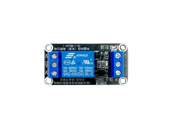
A relay is an electromechanical switch that uses an electromagnetic coil to open or close its internal contacts. This allows a low-power signal to control a high-power circuit, making it an essential component in many electronic and electrical systems. The "RELAY BLACK" designation may refer to the color of the relay's housing or a specific model variant. Relays are widely used in applications such as home automation, motor control, industrial equipment, and automotive systems.
Common use cases for the RELAY BLACK include:
- Switching high-power devices like motors, lights, or heaters.
- Isolating low-power control circuits from high-power loads.
- Enabling automation in smart home systems.
- Protecting sensitive electronics from high-current loads.
Explore Projects Built with RELAY BLACK


Explore Projects Built with RELAY BLACK
Technical Specifications
Below are the key technical details for the RELAY BLACK:
| Parameter | Value |
|---|---|
| Operating Voltage | 5V DC (coil voltage) |
| Switching Voltage | Up to 250V AC / 30V DC |
| Switching Current | Up to 10A |
| Coil Resistance | ~70Ω (for 5V coil) |
| Contact Type | SPDT (Single Pole Double Throw) |
| Contact Material | Silver alloy |
| Dimensions | 19mm x 15mm x 15mm |
| Insulation Resistance | ≥100MΩ at 500V DC |
| Dielectric Strength | 1500V AC (between coil and contacts) |
Pin Configuration
The RELAY BLACK typically has 5 pins. Below is the pinout and description:
| Pin Number | Name | Description |
|---|---|---|
| 1 | Coil (+) | Positive terminal of the electromagnetic coil. |
| 2 | Coil (-) | Negative terminal of the electromagnetic coil. |
| 3 | Common (COM) | Common terminal for the relay's switching contacts. |
| 4 | Normally Open (NO) | Contact that remains open until the relay is activated. |
| 5 | Normally Closed (NC) | Contact that remains closed until the relay is activated. |
Usage Instructions
How to Use the RELAY BLACK in a Circuit
- Power the Coil: Connect the coil pins (1 and 2) to a 5V DC power source. Use a transistor or MOSFET to control the coil if the relay is being driven by a microcontroller.
- Connect the Load:
- Connect the high-power device (e.g., motor, light) to the Common (COM) pin (Pin 3).
- Use the Normally Open (NO) pin (Pin 4) if you want the device to turn on when the relay is activated.
- Use the Normally Closed (NC) pin (Pin 5) if you want the device to turn off when the relay is activated.
- Control the Relay: Use a low-power control signal (e.g., from an Arduino or other microcontroller) to activate the relay by energizing the coil.
Important Considerations and Best Practices
- Diode Protection: Always connect a flyback diode (e.g., 1N4007) across the coil terminals to protect the driving circuit from voltage spikes caused by the relay's inductive load.
- Isolation: Ensure proper electrical isolation between the low-power control circuit and the high-power load.
- Current Ratings: Do not exceed the relay's maximum current and voltage ratings to avoid damage or failure.
- Heat Dissipation: If the relay is switching high currents frequently, ensure adequate ventilation or cooling to prevent overheating.
Example: Connecting RELAY BLACK to an Arduino UNO
Below is an example of how to control the RELAY BLACK using an Arduino UNO:
// Define the pin connected to the relay's control circuit
const int relayPin = 7; // Pin 7 is connected to the transistor base or relay module input

void setup() {
  pinMode(relayPin, OUTPUT); // Set the relay pin as an output
  digitalWrite(relayPin, LOW); // Ensure the relay is off at startup
}

void loop() {
  // Turn the relay on
  digitalWrite(relayPin, HIGH);
  delay(5000); // Keep the relay on for 5 seconds

  // Turn the relay off
  digitalWrite(relayPin, LOW);
  delay(5000); // Keep the relay off for 5 seconds
}
Note: Use a transistor (e.g., 2N2222) or a relay module to interface the Arduino with the relay, as the Arduino cannot directly supply enough current to drive the relay coil.
Troubleshooting and FAQs
Common Issues and Solutions
Relay Not Activating:
- Cause: Insufficient voltage or current to the coil.
- Solution: Verify the power supply to the coil and ensure it matches the relay's specifications.
Relay Stuck in One State:
- Cause: Damaged or worn-out contacts.
- Solution: Replace the relay if the contacts are no longer functional.
High-Power Load Not Switching:
- Cause: Incorrect wiring of the load to the relay's contacts.
- Solution: Double-check the connections to the COM, NO, and NC pins.
Microcontroller Resetting When Relay Activates:
- Cause: Voltage spikes from the relay coil affecting the microcontroller.
- Solution: Add a flyback diode across the coil and use proper decoupling capacitors near the microcontroller.
FAQs
Q: Can I use the RELAY BLACK with a 3.3V microcontroller?
A: Yes, but you will need a transistor or relay driver circuit to step up the control signal to 5V.Q: What is the lifespan of the RELAY BLACK?
A: The relay typically has a mechanical lifespan of over 10 million operations and an electrical lifespan of around 100,000 operations, depending on the load.Q: Can the RELAY BLACK switch DC loads?
A: Yes, it can switch DC loads up to 30V DC, provided the current does not exceed 10A.Q: Is the RELAY BLACK suitable for switching inductive loads?
A: Yes, but ensure you use proper snubber circuits or flyback diodes to protect the relay contacts from arcing.
This concludes the documentation for the RELAY BLACK.